Electro-optical reader with improved laser intensity modulation over extended working range

a laser intensity modulation and optical reader technology, applied in the field of optical readers, can solve the problems of preventing accurate reading of symbols, affecting the accuracy of reading symbols, and increasing the working range of lower density symbols, so as to achieve the effect of increasing the working range of optical readers

Inactive Publication Date: 2006-01-26
SYMBOL TECH INC
View PDF10 Cites 16 Cited by
  • Summary
  • Abstract
  • Description
  • Claims
  • Application Information

AI Technical Summary

Benefits of technology

[0018] Accordingly, it is a general object of this inventi

Problems solved by technology

Printing of the denser symbols on an appropriate medium is exacting and, thus, is more expensive than printing low density symbols with larger elements.
However, as the distance between the reader and the symbol moves out of the working range of the reader, which is typically only a few inches in length, the Gaussian distribution of the beam spot greatly widens, preventing accurate reading of a symbol.
However, where such a beam is designed to improve performance in scanning a certain bar code density, the corresponding working range of lower density symbols is not increased significantly or at all, being limited by the distance where the beam breaks into a donut-like distribution.

Method used


Image

  • Electro-optical reader with improved laser intensity modulation over extended working range
  • Electro-optical reader with improved laser intensity modulation over extended working range
  • Electro-optical reader with improved laser intensity modulation over extended working range

Examples


Embodiment Construction

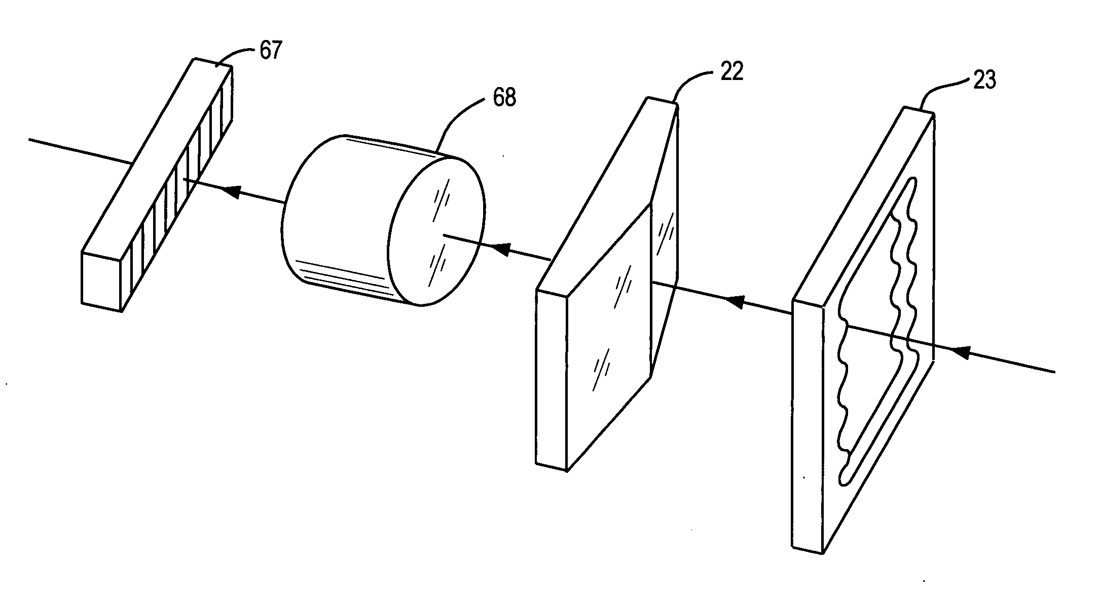
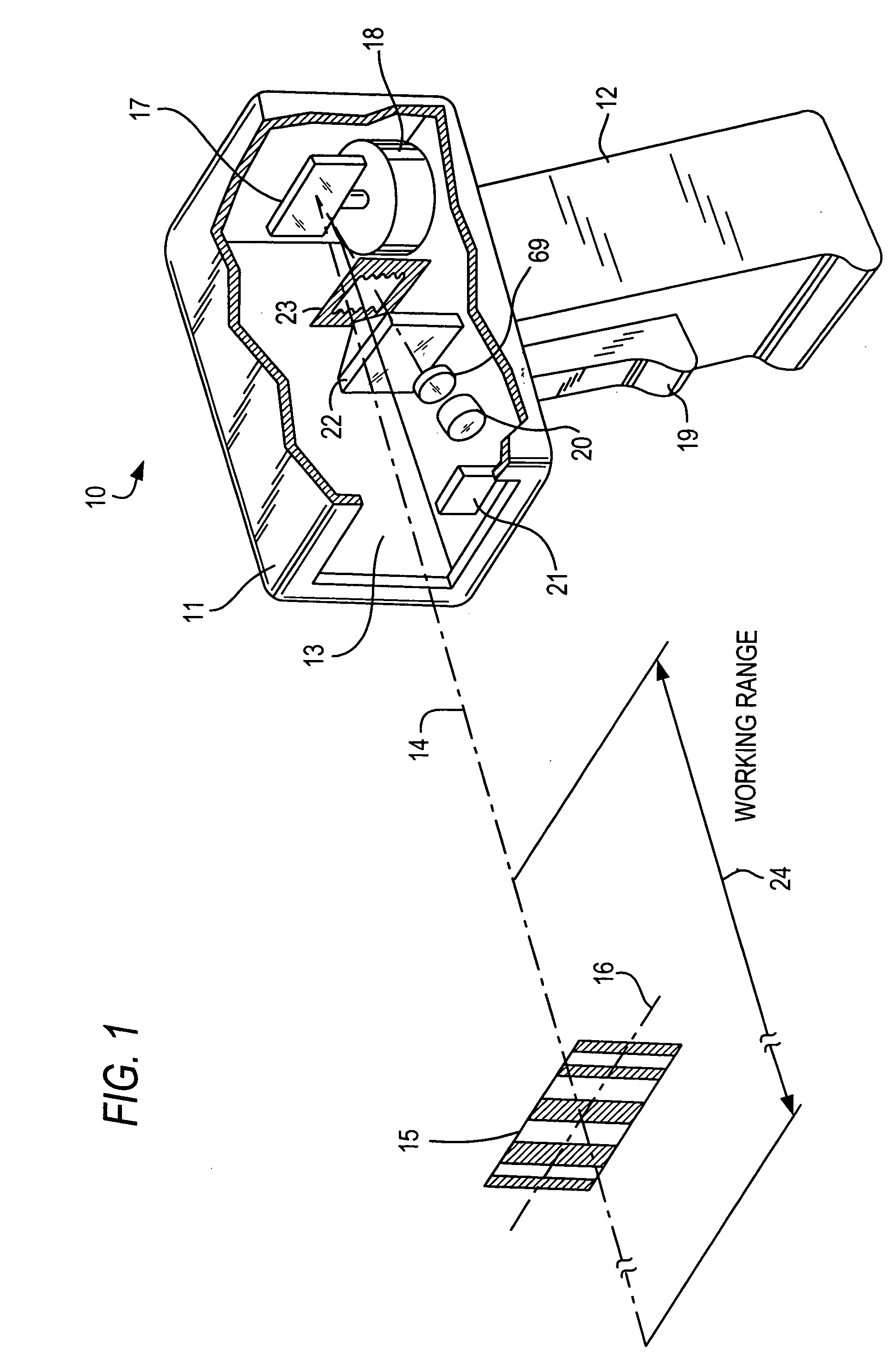
[0048] As used herein, the term “symbol” broadly encompasses not only symbol patterns composed of alternating bars and spaces of various widths as commonly referred to as bar code symbols, but also other one- or two-dimensional graphic patterns, as well as alphanumeric characters. In general, the term “symbol” may apply to any type of pattern or indicia which may be recognized or identified either by scanning a light beam and detecting reflected or scattered light as a representation of variations in light reflectivity at various points of the pattern or indicia, or by scanning a field of view and imaging light returning from the symbol onto a sensor array. FIG. 1 shows an indicia 15 as one example of a “symbol” which the present invention can read.

[0049]FIG. 1 depicts a handheld laser scanner device 10 for reading symbols. The laser scanner device 10 includes a housing that is generally of the type shown in the above-mentioned patents having a barrel portion 11 and a handle 12. Al...


PUM


Abstract

The combination of a rooftop optical element and a soft edge aperture stop, as well as the introduction of a negative spherical aberration in a positive focusing lens, improve working distance and depth of focus in both moving beam and imaging readers for electro-optically reading indicia such as bar code symbols, especially for close-in symbols, and moreover tend to reduce undesirable light intensity modulation in the beam profile thereby improving reader performance.

Description

BACKGROUND OF THE INVENTION [0001] 1. Field of the Invention [0002] The present invention generally relates to electro-optical readers, such as laser scanners and imagers and, more particularly, to improved aperture stops and optical components for improving laser intensity modulation over an extended working range or depth of focus in which indicia, such as bar code symbols, are read. [0003] 2. Description of the Related Art [0004] Bar code readers are known in the prior art for reading various symbologies such as Universal Product Code (UPC) bar code symbols appearing on a label, or on the surfaces of an article. The bar code symbol itself is a coded pattern of graphic indicia comprised of a series of bars of various widths spaced apart from one another to bound spaces of various widths, the bars and spaces having different light reflecting characteristics. The readers electro-optically transform the graphic indicia into electrical signals, which are decoded into information, typi...

Claims


Application Information

Patent Timeline
IPC IPC(8): G06K7/10G02B26/08
CPCG06K7/10831G06K7/10683
Inventor VINOGRADOV, IGORGUREVICH, VLADIMIRSHI, DAVID TSIMADEJ, DARIUSZ J.PATEL, MEHUL M.BARKAN, EDWARDZHANG, HENG
Owner SYMBOL TECH INC
Why Eureka
Try Eureka