Temperature compensating insert and integral thermal compensation for a smart material actuator

a smart material actuator and temperature compensation technology, applied in piezoelectric/electrostrictive/magnetostrictive devices, electrical apparatus, electric motors, etc., can solve the problems of increasing the method suffers from several problems, and the compensating element inserted between the main body and the smart material increases the overall length of the actuator, so as to reduce or eliminate the movement of the arms

Inactive Publication Date: 2006-01-26
VIKING TECH L C
View PDF1 Cites 10 Cited by
  • Summary
  • Abstract
  • Description
  • Claims
  • Application Information

AI Technical Summary

Benefits of technology

[0013] An apparatus according to the present invention includes a support structure with first and second arms spaced apart from one another. A smart material actuator, such as a piezoelectric actuator, moves the first and second arms with respect to one another in response to expansion and contraction of the actuator. Means for compensating for the effects of different thermal coefficients of expansion of the materials used in the support structure and actuator is provided to reduce or eliminate movement of the arms resulting from variations in working temperature and / or ambient temperature.

Problems solved by technology

This method suffers from several problems.
One such problem is the length of the compensating element inserted between the main body and the smart material increases the overall length of the actuator.
This is a difficult combination to achieve with inexpensive materials.
This system uses several parts, all of which are complex, and costly to machine and increases the overall size making it less desirable.
This difference in CTE between the steel mechanical structure and the CMA will result in a change in the force applied on the amplifying mechanism during a change in ambient temperature conditions.
Such a thermal effect can result in an improper operation of a device, such as the previously mentioned valve, using such an actuating mechanism.
This reduction in stroke or force could cause an associated valve to demonstrate a flow rate that is less than nominal or inadequate sealing force resulting in leaking.
However, it does so with a severe impact to multiple characteristics, for example structural reliability, production complexity and cost.
These will, in turn, limit the potential physical size and work capability.
Therefore, also limiting the applicability of such an approach.
In general, this approach adds substantial complexity and cost to the actuation system.

Method used


Image

  • Temperature compensating insert and integral thermal compensation for a smart material actuator
  • Temperature compensating insert and integral thermal compensation for a smart material actuator
  • Temperature compensating insert and integral thermal compensation for a smart material actuator

Examples


Embodiment Construction

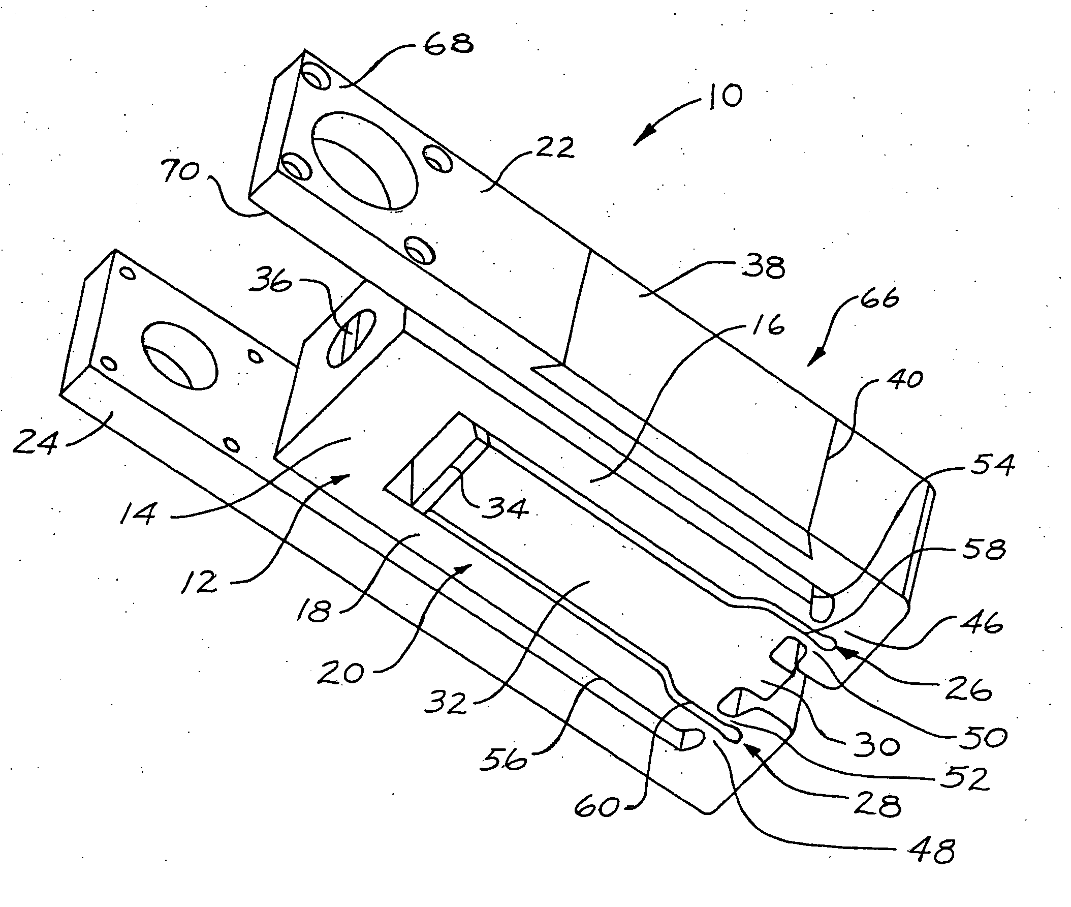
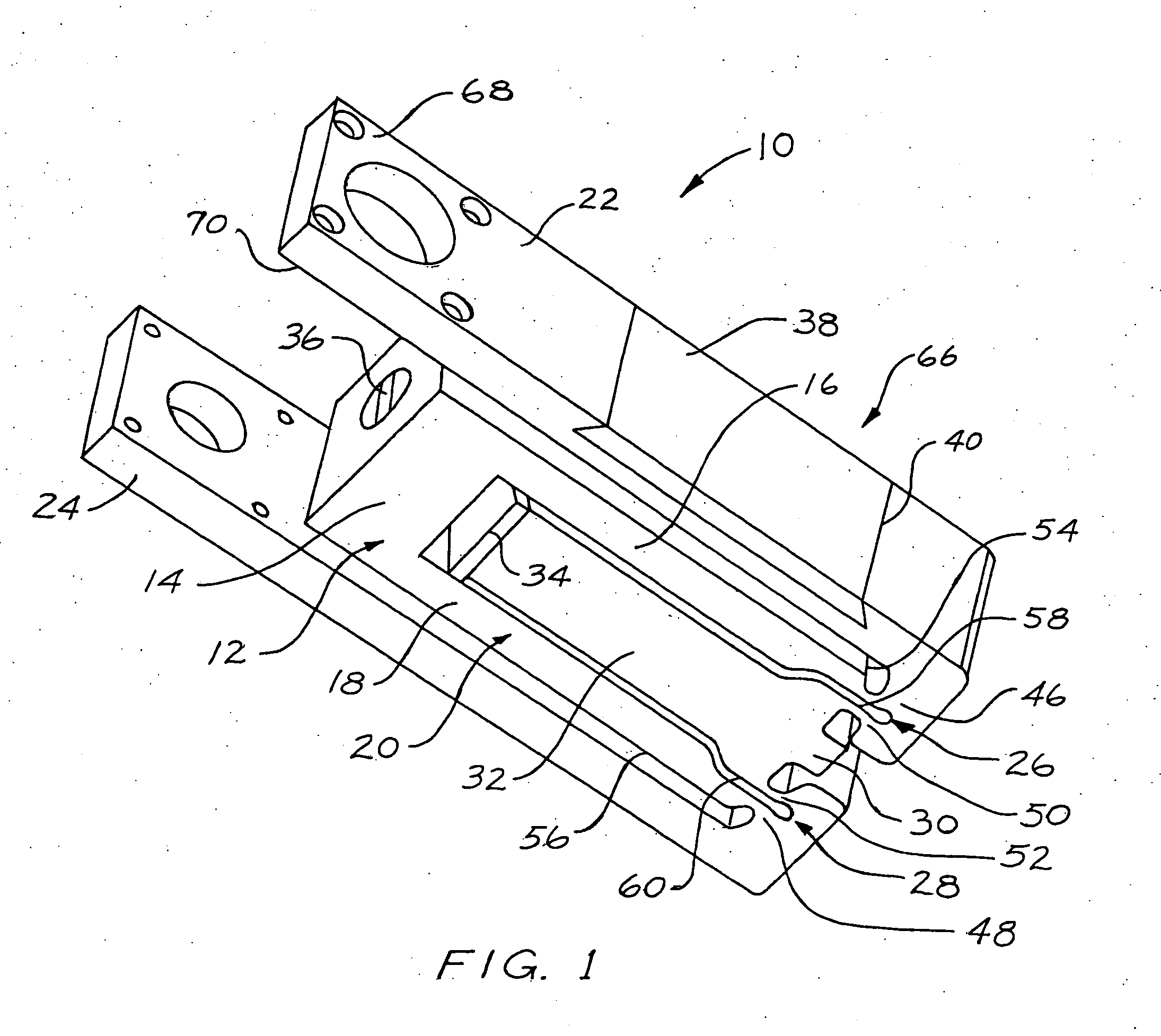
[0045] Referring now to FIG. 1, a perspective view of one embodiment of an apparatus 10 is illustrated having a support structure 12 including a non-flexing web portion 14 extending between an upper and a lower pair of rigid non-flexing side portions 16, 18 forming a C-shaped portion 20. At least one pivotable arm portion, such as a first arm portion, 22, or 24 is pivotably connected via a corresponding living integral hinge portion 26, or 28 to a corresponding side portion 16, or 18. Another pivotable arm, such as a second arm portion 24 can be optionally connected via a corresponding living integral hinge portion 28 to the other rigid side portion 18, if two opposing arms 22, 24 are desired. A force transfer member 30 includes a surface engagable with one end of a smart material actuator 32. The opposite end of the smart material actuator 32 engages with an adjustable seat 34. Adjustable seat 34 can be supported by an adjustable support screw 36, connected through the support stru...


PUM


Abstract

An apparatus can have a smart material actuator, a support structure and at least one temperature compensating material insert, either externally mounted to the support structure, integrally formed with the support structure, or any combination thereof. The structure of the apparatus can be formed of various materials with different Coefficient of Thermal Expansion (CTE). The apparatus can include a mechanically leveraged electrically stimulated smart material. The support structure and actuator can be susceptible to the effects of differences in thermal coefficients of expansion of the materials used in the construction. A method for dimensioning and placement of a compensating insert with respect to the support structure provides an accurate and cost effective compensating insert. Furthermore, a method of compensating for differences in the rate of thermal expansion in one or more elements of an actuator is included with the present invention.

Description

CROSS-REFERENCE TO RELATED APPLICATIONS [0001] This application is a continuation-in-part of patent application Ser. No. 10 / 613,138 filed on Jul. 3, 2003, which claimed the benefit of provisional application Ser. No. 60 / 393,799 filed Jul. 3, 2002, and patent application Ser. No. 10 / 993,118 filed on Nov. 19, 2004, which claimed the benefit of provisional application Ser. No. 60 / 523,808 filed Nov. 20, 2003, all of which are incorporated by reference herein in their entirety.FIELD OF THE INVENTION [0002] The present invention relates to a temperature compensating apparatus and method for a mechanically leveraged smart material actuator. BACKGROUND OF THE INVENTION [0003] Various smart material actuator technologies have been developed for a wide range of applications in different industries. One component used in this type of actuator is an electrically stimulated smart material actuator. These smart material actuators when electrically stimulated change shape. This shape change can be...

Claims


Application Information

Patent Timeline
Patent Type & Authority Applications(United States)
IPC IPC(8): H01L41/08H01L41/09
CPCH02N2/043H10N30/00H10N30/20
Inventor MOLER, JEFFBUGEL, JOHN A.OUDSHOORN, MARK
Owner VIKING TECH L C
Why Eureka
Try Eureka