Fuse blow-out dual LED indicator

Inactive Publication Date: 2006-01-26
SMITH JERRY L
View PDF10 Cites 42 Cited by
  • Summary
  • Abstract
  • Description
  • Claims
  • Application Information

AI Technical Summary

Benefits of technology

[0029] An advantage of the present invention is that when a fuse is blown it clearly indicates that the fuse is blown no matter how the fuse is installed
[0030] Another advantage of the present invention is that, when changing the bad fuse, the mechanic or owner does not have to be conscious of the polarity because the LED indicator will light re

Problems solved by technology

When a fuse reaches overload, the link melts due to high heat caused by excessive current moving through the fuse, this in turn interrupts the electrical circuit and the electrical equipment previously supplied with electricity ceases to function.
Prior art attempts to pr

Method used


Image

  • Fuse blow-out dual LED indicator
  • Fuse blow-out dual LED indicator
  • Fuse blow-out dual LED indicator

Examples


Example

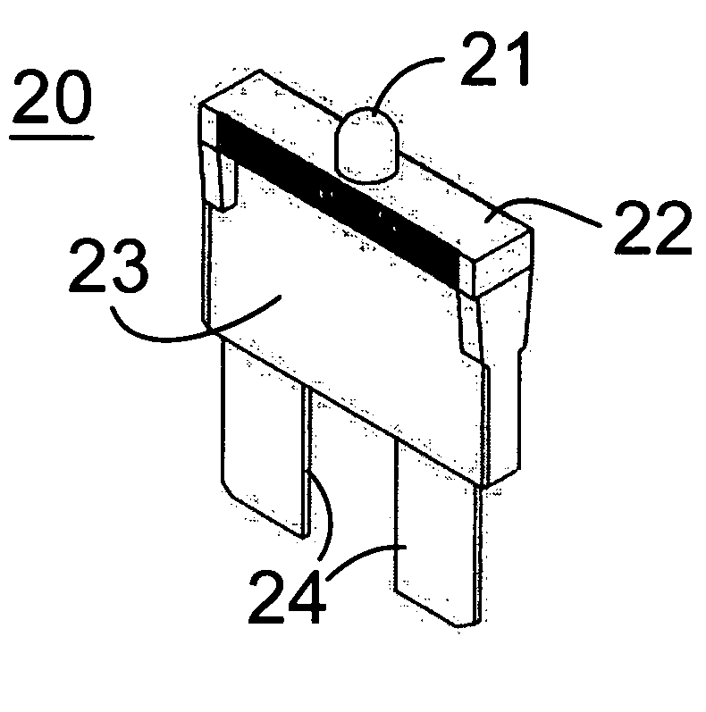
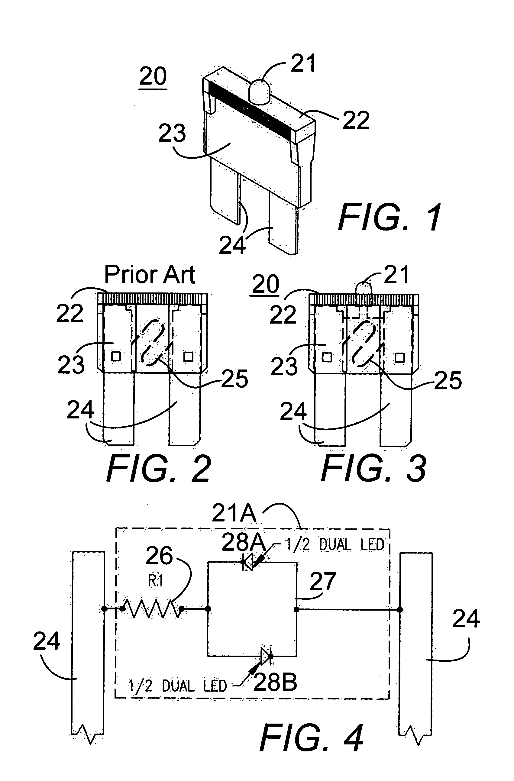
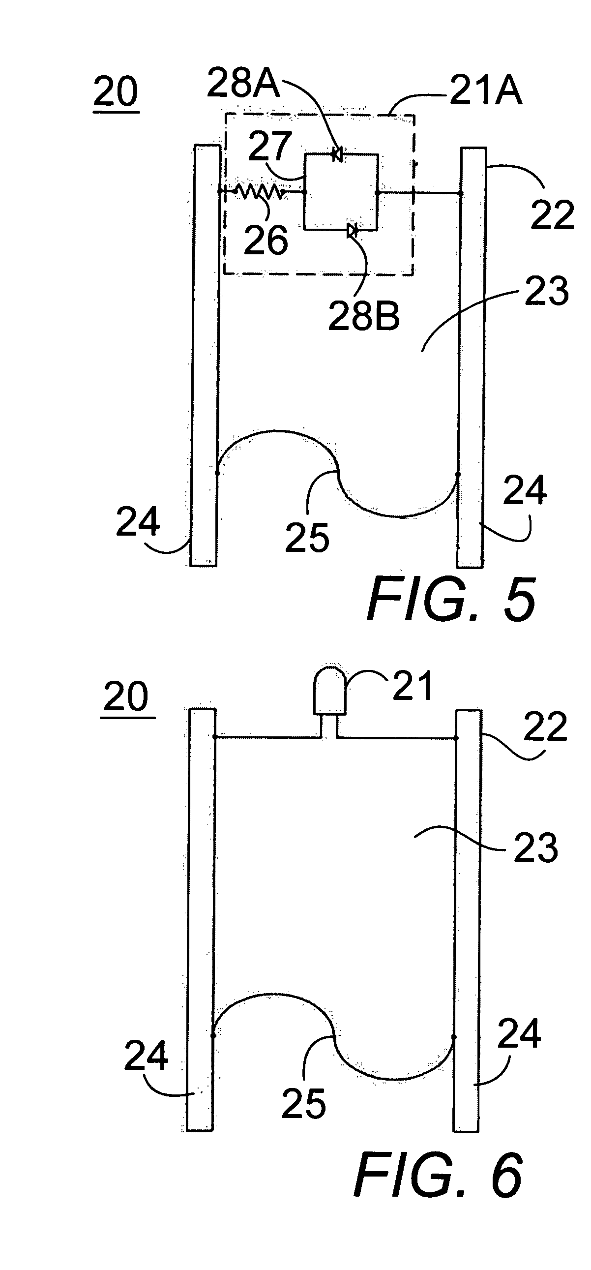
[0043] In FIGS. 1 and 3 through 9, a blown fuse indicator light device 20 and 20A comprises a dual bipolar LED indicator light circuit 21A between the blades 24 of a blade fuse in parallel with the fuse link 25. When the fuse link blows, the dual bipolar LED indicator light circuit lights to point out a blown fuse. The dual bipolar LED indicator light circuit 21A has parallel dual bipolar light emitting diode (LED) indicators 28A and 28B in series with an integrated resistor 26 for showing if the fuse is opened or blown. The dual bipolar LED indicators allow the fuse to be inserted in either direction and may be built into a blade fuse, as in FIGS. 1 and 3-6, or snapped onto a blade fuse as an attachment as in FIGS. 7 through 9.

[0044] The blown fuse indicator light device 20 for a vehicle fuse comprises two insertion blades 24, which insert into an electrical circuit to complete the circuit, and a fuse link 25 that forms an electrical connection between the blades. The fuse link is...


PUM


Abstract

A dual bipolar LED indicator light circuit is connected between the blades of a blade fuse in parallel with the fuse link. When the fuse link blows, one of the LEDs lights to indicate a blown fuse. Parallel dual bipolar light emitting diode (LED) indicators are in series with an integrated resistor. The fuse may be inserted in either direction without concern for polarity. The indicator light circuit may be built into a blade fuse, or snapped onto an existing blade fuse as an attachment.

Description

CLAIM OF PROVISIONAL APPLICATION RIGHTS [0001] This application claims the benefit of U.S. Provisional Patent Application No. 60 / 590,949, filed on Jul. 26, 2004.BACKGROUND OF THE INVENTION [0002] 1. Field of the Invention [0003] The present invention relates to overcurrent protection devices and particularly to a blade fuse having a dual bipolar light emitting diode (LED) indicator and an integrated resistor for showing if the fuse is opened or blown, which allows the fuse to be inserted in either direction and which may be built into a blade fuse or snapped onto a blade fuse as an attachment. [0004] 2. Description of the Prior Art [0005] Fuses are widely used as overcurrent protection devices to protect the wiring and battery to prevent costly damage to electrical circuits. Fuse terminals typically form an electrical connection between an electrical power source and an electrical component or a combination of components arranged in an electrical circuit. [0006] Electrical equipment...

Claims


Application Information

Patent Timeline
IPC IPC(8): H01H85/30H01H85/32
CPCH01H85/32
Inventor SMITH, JERRY L.
Owner SMITH JERRY L
Why Eureka
Try Eureka