Inkjet print head and manufacturing method thereof

a printing head and print head technology, applied in printing, inking apparatus, etc., can solve the problems of unreliable conduction, complicated bonding work, wire disconnection, etc., and achieve the effect of simplifying the electrical connection

Inactive Publication Date: 2006-01-26
KONICA MINOLTA INC
View PDF2 Cites 26 Cited by
  • Summary
  • Abstract
  • Description
  • Claims
  • Application Information

AI Technical Summary

Benefits of technology

[0011] Another object of the present invention is to provide an improved version of inkjet print head wherein the front surface and back surface of the head chip are located face to face with each other.
[0012] A further object of the present invention is to simplify the electrical connection between the connection wire led from the drive electrode of each ink channel an...

Problems solved by technology

The portions in contact therewith tend to cause wire disconnection.
This raises a problem with unreliable conduction.
As described in the Official Gazette of Japanes...

Method used


Image

  • Inkjet print head and manufacturing method thereof
  • Inkjet print head and manufacturing method thereof
  • Inkjet print head and manufacturing method thereof

Examples


Embodiment Construction

[0037] The following describes the embodiments according to the present invention with reference to drawings:

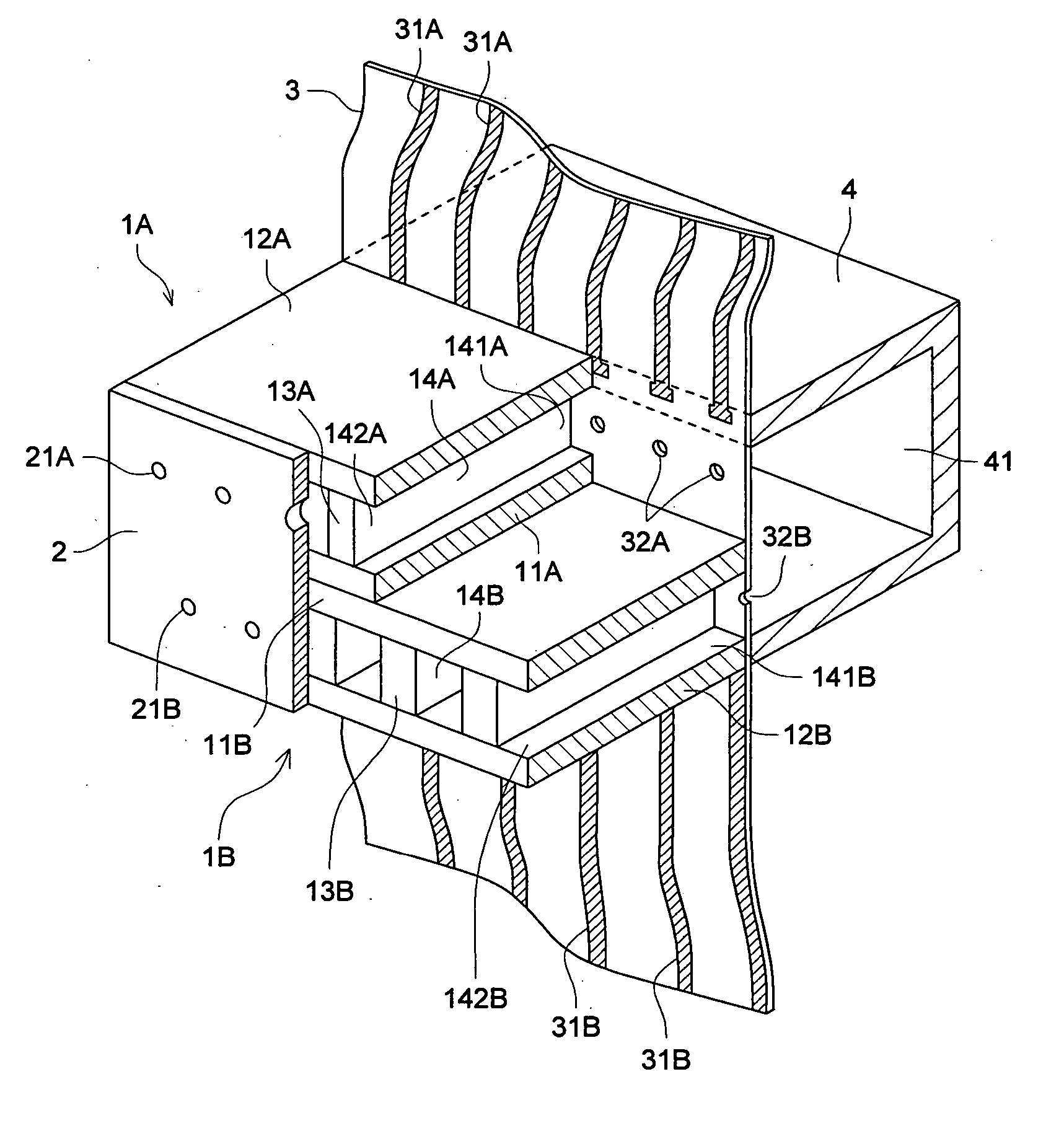
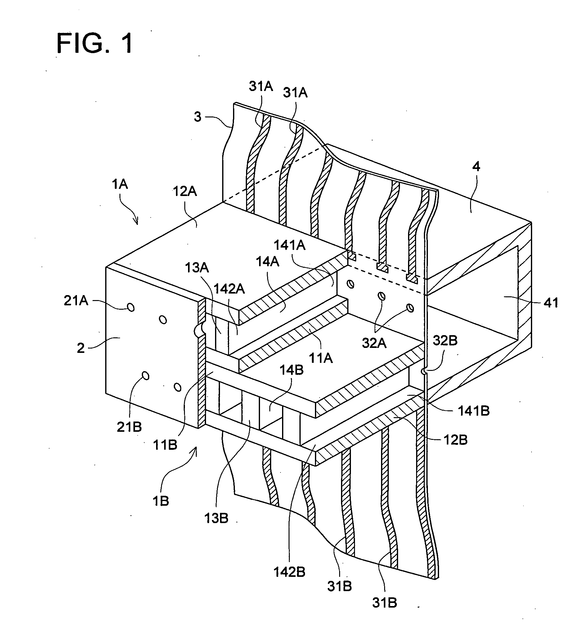
[0038]FIG. 1 is a perspective view in cross section of an example of an inkjet print head. In FIG. 1, 1A and 1B denote head chips, and 2 indicates a nozzle plate connected to the front surface of the head chips 1A and 1B. Numeral 3 shows a flexible wiring board with aperture connected to the back surface of the head chips 1A and 1B, and 4 denotes an ink manifold connected opposite to each of the head chips 1A and 1B in the flexible wiring board 3.

[0039] In this specification, the “front surface” refers to the surface on the side where an ink droplet is ejected from the head chip (ink channel), and the “back surface” refers to the surface on the opposite side. The upper and lower outer surfaces in the drawing sandwiching the channels arranged in parallel in the head chip are called “top surface” and “bottom surface”, respectively.

[0040] The following describes the method fo...


PUM


Abstract

an inkjet print head wherein the surface (front surface) for ejecting ink droplets coming from an ink channel partitioned by a drive wall composed of a piezoelectric device is arranged opposite to the surface (back surface) for supplying ink coming to the ink channel. The connection electrode for driving the piezoelectric device is pulled out to the back surface, and the back surface is a photosensitive glass substrate wherein the ink feed apertures manufactured by exposure and etching process, and the drive wires electrically connected with the connection electrode are formed.

Description

BACKGROUND OF THE INVENTION [0001] 1. Field of the Invention [0002] The present invention relates to an inkjet print head wherein the surface (front surface) for ejecting an ink droplet from an ink channel partitioned by a drive wall composed of piezoelectric devices and the surface (back surface) for supplying ink to the aforementioned ink channel are located face to face with each other. [0003] 2. Description of the Related Art [0004] One of the prior art inkjet print heads is a shared wall share mode inkjet print head wherein voltage is applied to the drive wall partitioning an ink channel so that the drive wall is shear-deformed, and the pressure resulting therefrom is utilized to allow ink of the ink channel to be ejected through a nozzle. The Official Gazette of Japanese Patent Tokkai 2002-264342 discloses a share mode inkjet print head, as one of these inkjet print heads, wherein the surface (front surface) for ejecting ink from an ink channel and the surface (back surface) f...

Claims


Application Information

Patent Timeline
IPC IPC(8): B41J2/14
CPCB41J2/14209B41J2/1609B41J2002/14491B41J2/1631B41J2202/18B41J2/1626
Inventor OKUNO, TETSUO
Owner KONICA MINOLTA INC
Why Eureka
Try Eureka