Eureka AIR delivers breakthrough ideas for toughest innovation challenges, trusted by R&D personnel around the world.

Pad printer cartridge and reciprocating table having bearing members

Inactive Publication Date: 2005-02-22
PRINTA SYST
View PDF8 Cites 5 Cited by
  • Summary
  • Abstract
  • Description
  • Claims
  • Application Information

AI Technical Summary

Benefits of technology

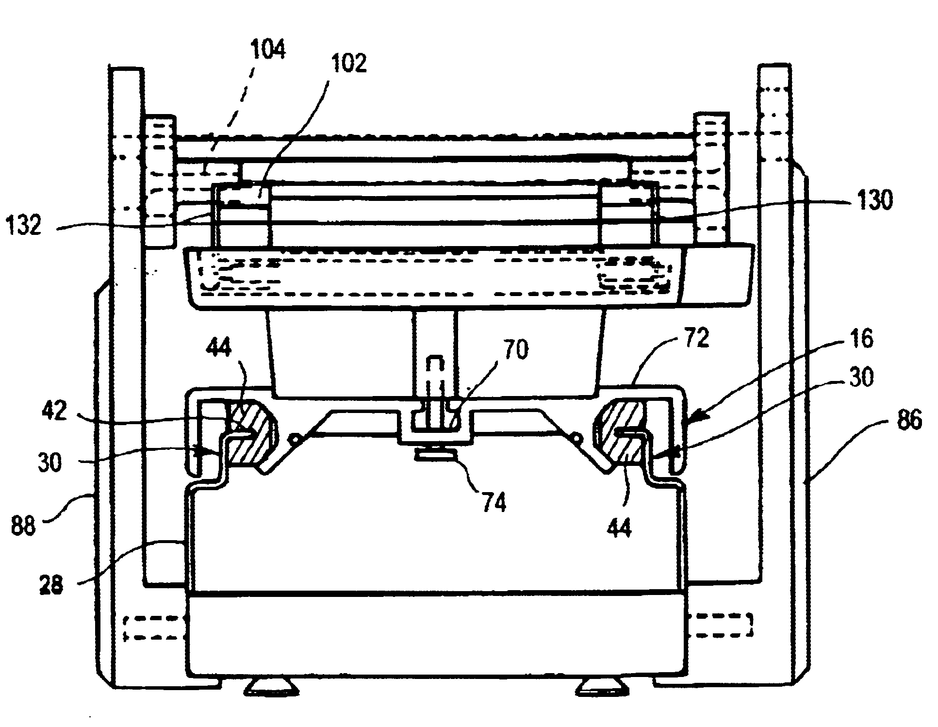
The invention is an improved version of a pad printer. One part of the improvement relates to the way a reciprocating pad printer table carries a print tray or “ink tray unit,” and a turntable for holding an item that is to be printed. The table is mounted to a base by a pair of parallel, spaced-apart bearing members. The bearing members are elongated in form and mounted directly to the base. They have inwardly directed surfaces with a defined geometry such that one bearing faces the other. The table member has outwardly facing channels with surfaces that slidingly mate with the bearing member surfaces. The bearing members are preferably made of nylon, high-density plastic, or another material which has a low coefficient of friction. This enables the table to slide easily along the bearing members.
Alternatively the entire roller and wipe cartridge can be replaced by a sealed ink cup. Sealed ink cups are known in the art. They have an internal reservoir of ink, eliminating the need for a separate supply of ink in the ink reservoir of the ink tray unit. In operation, the ink cup is positioned over the ink tray unit. Ink in the cup diffuses from openings located on the flat, bottom surface of the ink cup and on to the image to be inked: As the pad printer table is moved back and forth, the bottom surface of the ink cup swipes across and inks the image.

Problems solved by technology

Commercial printers are very large machines and tend to be very expensive.
Other companies do not print items at volumes that justify the expense of a commercial printer.
While this type of construction certainly works well, it is also an overdesign relative to the way the typical pad printer is used.
It is also an expensive component for the pad printer manufacturer.
Second, the conventional pad printer requires essentially three operations relating to table movement in order to transfer the image from the print plate (apart from the upward and downward operation of the printing pad).

Method used


Image

  • Pad printer cartridge and reciprocating table having bearing members
  • Pad printer cartridge and reciprocating table having bearing members
  • Pad printer cartridge and reciprocating table having bearing members

Examples


Embodiment Construction

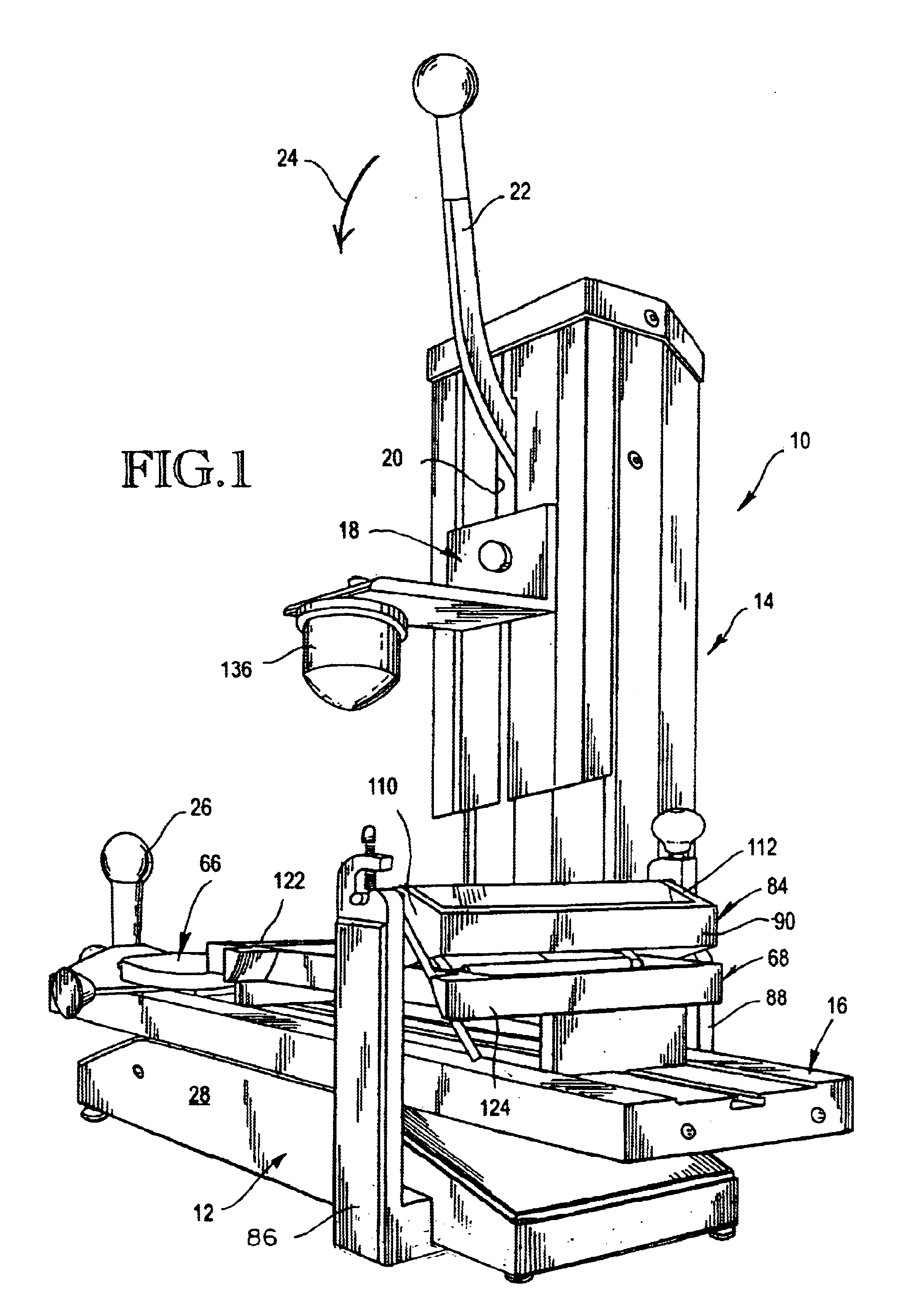
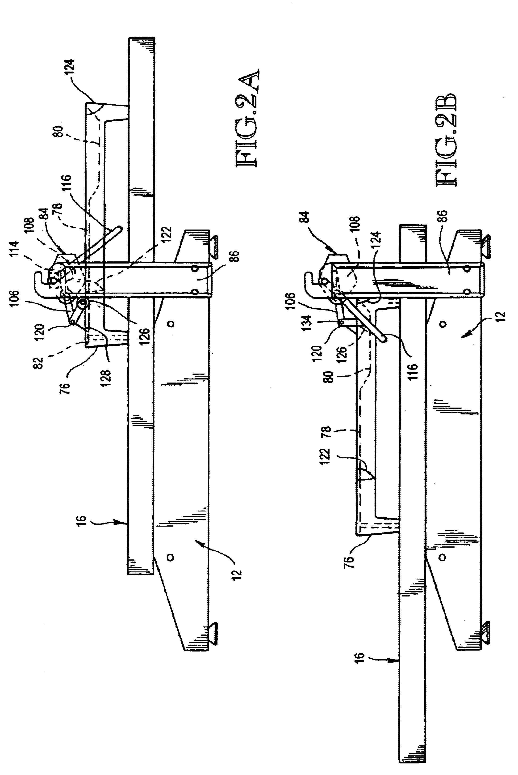
Referring to the drawings, and first to FIG. 1, shown generally at 10 is a pad printer constructed in accordance with a preferred embodiment of the invention. The printer 10 has a base portion 12 and a tower portion 14. The base portion (“base”) 12 carries a reciprocating table 16 which is slidingly mounted to the base in a manner that will be described later. The tower portion (“tower”) 14 carries a printer pad support 18 which moves vertically upwardly and downwardly along a slot 20.

Upward and downward movement of the support 18 is controlled by a crank arm 22. When the crank arm 22 is pulled down in the direction indicated by arrow 24, it forces the pad support down along slot 20. The arm 22 is spring biased so that when it is released, the support 18 automatically returns to the position shown in FIG. 1. While the interior of the tower 14 includes an arrangement of guide rods, one or more springs, and mechanical connections between the arm 22 and support 18, this structure is co...


PUM


Abstract

An improved table and ink wipe cartridge for a pad printer consists of a table mounted to a base by a pair of parallel, nylon bearings. The bearings enable the table to slide back and forth easily without requiring conventional ballbearings and guides. The cartridge automatically rolls and wipes ink on a print tray carried by the table.

Description

TECHNICAL FIELDThis invention relates to pad printers. More particularly, it relates to an improved reciprocating table and an improved inking and wiping structure for a pad printer.BACKGROUND OF THE INVENTIONPad printing devices have been in existence for a long period of time. Pad printers are typically used to transfer custom images from an ink pad to a non-planar surface. The most familiar use of pad printers is probably the printing of company names and logos on coffee cups, pens, golf balls, and the like.Many pad printers are fully automatic, commercial printers that are capable of printing items in large volume. Commercial printers are very large machines and tend to be very expensive. At today's prices, some commercial printers cost as much as $100,000.The expense of a commercial printer is justified for some companies. A golf ball manufacturer, for example, needs a commercial printer because it has to print its trademarks and model numbers on many thousands or millions of g...

Claims


Application Information

Patent Timeline
IPC IPC(8): B41F17/00
CPCB41F17/001
Inventor GOSS, DUKE W.
Owner PRINTA SYST
Why Eureka
Eureka Blog
Learn More