
Minisize air lift pump with low power consumption air guide structure

An air guide structure, low power consumption technology, applied in the direction of pumps, multi-stage pumps, pump components, etc., can solve the problems of twists and turns, large air resistance, increased power consumption, etc., to achieve a simple assembly process, smooth air flow channels , the effect of improving the measurement accuracy

Inactive Publication Date: 2008-05-14
SHENZHEN KINGYIELD TECH
View PDF4 Cites 0 Cited by
  • Summary
  • Abstract
  • Description
  • Claims
  • Application Information

AI Technical Summary

Problems solved by technology

[0003] Although this micropump has overcome some deficiencies of commonly used micropumps, it is not perfect and still has the following deficiencies: 1. The air path before the air enters the airbag is too tortuous, and the tortuous air path has large air resistance and large energy consumption
2. When the airbag is under pressure, because the one-way valve of the air inlet is far away from the airbag, it is difficult to directly reach the airbag under pressure, and the one-way valve cannot be closed in time, and there is a phenomenon of air backflow, which brings about the weakness of poor air tightness. If it is used for blood pressure meter, will affect the measurement accuracy of blood pressure
3. The briquetting block is equipped with an air intake path and an air outlet path at the same time, which increases the difficulty and cost of the briquetting process
4. The transmission mechanism is too cumbersome, and the cumbersome transmission mechanism will produce up and down serial motion, which will affect the life of the micro pump, increase power consumption, and be accompanied by loud noise
This Japanese patent application has the following deficiencies: 1. The three-dimensional structure of the one-way valve itself has the disadvantages of poor airtightness, difficult assembly, and difficulty in guaranteeing the process.
2. The air path before the air enters the airbag is too tortuous, and the tortuous air path has large air resistance and high energy consumption
3. When the airbag is under pressure, because the one-way valve of the air inlet is far away from the airbag and needs to turn, the airbag is difficult to reach directly under pressure, and the one-way valve cannot be closed in time, and there is a phenomenon of air backflow, which brings about the weakness of poor airtightness. If it is used in a sphygmomanometer, it will affect the measurement accuracy of blood pressure
4. The briquetting block is provided with an air intake path and an air outlet path at the same time, which increases the difficulty and cost of the briquetting process
5. The transmission mechanism is too cumbersome. On the one hand, the cumbersome transmission mechanism will generate noise, on the other hand, it will make the production process cumbersome and difficult to control the production quality, thus increasing the production cost

Method used


Image

  • Minisize air lift pump with low power consumption air guide structure
  • Minisize air lift pump with low power consumption air guide structure
  • Minisize air lift pump with low power consumption air guide structure

Examples


Embodiment Construction

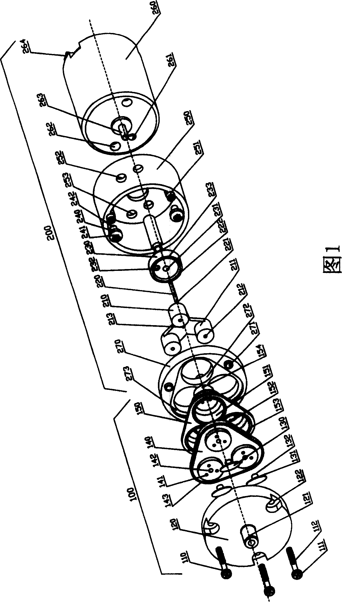
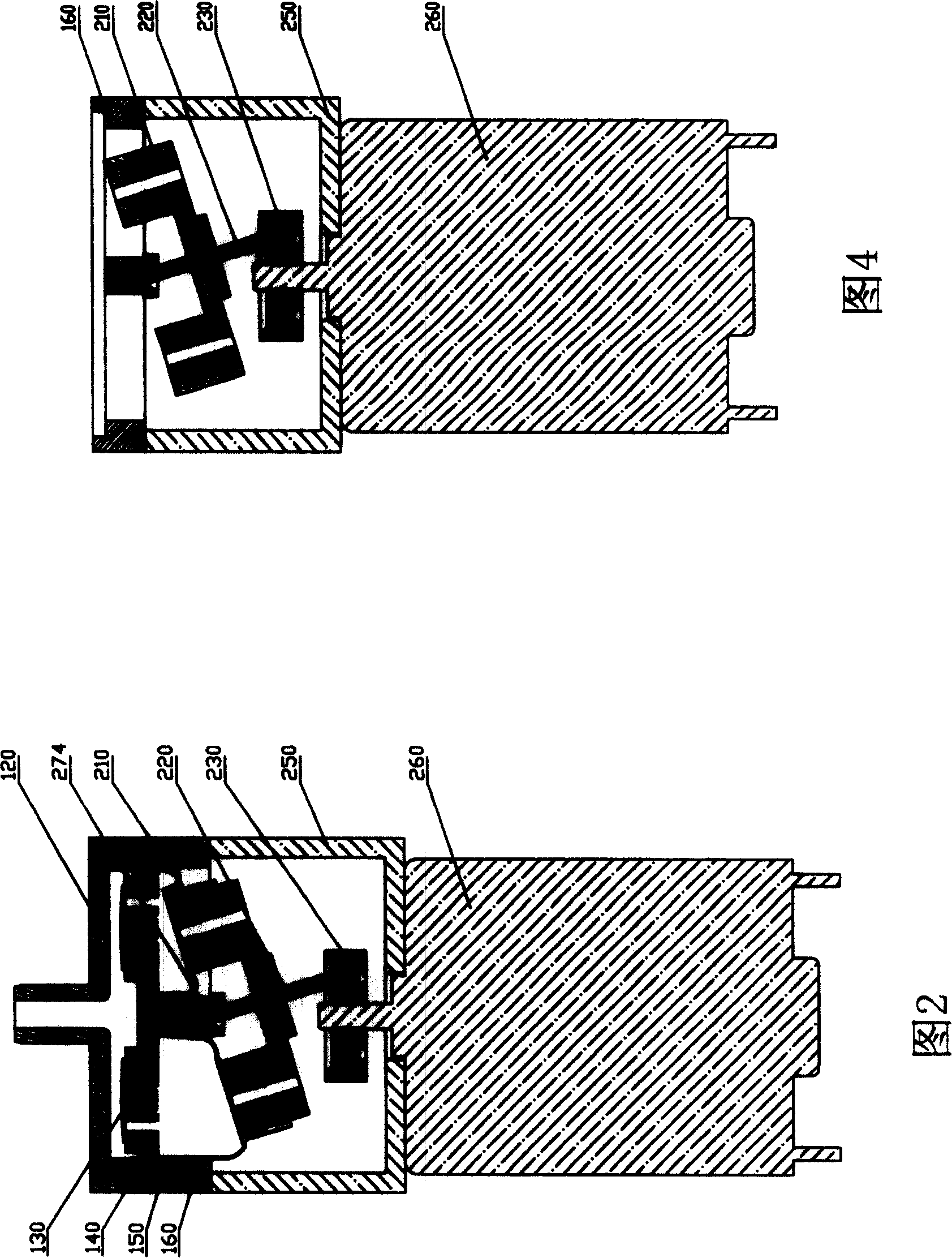
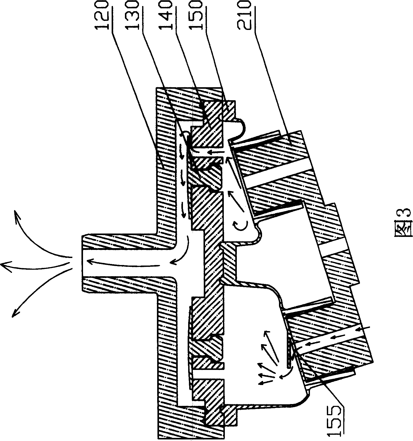
[0032] 1 and 2, the miniature pneumatic pump with a low power consumption air diversion structure of the present invention is composed of a gas diversion assembly 100 and a transmission assembly 200.

[0033]Please also refer to FIG. 3, the transmission assembly 200 includes a motor 260, a base 250, a motor fixing screw 240, an eccentric wheel, a transmission shaft 220, a compression piece 210, and a piston bracket 270. The motor 260 has an air inlet 261, and the bottom of the motor 260 has a motor terminal 264. The base 250 is provided with an assembly positioning hole 251 and an air inlet 252 for integral assembly. The air inlet 252 and the air inlet 261 are used to guide the piston The cavity 151 is supplied with external air, and the base 250 is fixed on the motor 260 through the cooperation of two motor fixing screws 240 with spring washers 241 and the screw fixing holes 253 on the motor 260. A spherical hole 274 is opened at the center of the rear of the piston bracket 270 o...


PUM


Abstract

The invention discloses a micro pneumatic pump of low power consumption air guiding structure, wherein the gas guiding component contains air cock, briquette and piston body with multiple small piston cavities; the air hole is opened on the briquette in connection with the air cock; the one-way air vent valve is fixed on the air hole; the air vent hole connects each piston cavity to form one-way air vent passage; the driving component contains motor, eccentric wheel, compression piece, driving shaft and piston rack; the elastic fixation case and air orifice are set under each piston cavity with one-way valve on the air orifice; the corresponding piston installment position and air orifice are set on the compression piece, which encase the elastic fixation case tightly; the one-way air-in passage is composed of air orifice under each piston cavity, one-way air orifice valve and air orifice on the compression piece; the motor compresses the piston cavity on the piston rack through the eccentric wheel and driving compression piece of driving shaft.

Description

【Technical Field】 [0001] The invention relates to a pneumatic pump, in particular to a miniature pneumatic pump with a low power consumption air diversion structure, which is very suitable for miniature pneumatic pumps used in electronic blood pressure monitors and other medical and health care products. 【Background technique】 [0002] On October 24, 2001, the Chinese Patent Office authorized and announced a utility model patent with the title of "Micropump Air Diversion Mechanism" and the patent number ZL00225848. This mechanism mainly includes a motor assembly, a compression part, and an air collection part. Among them, the connecting rod of the compression part is inserted into the eccentric hole of the motor rotating part, and the connecting rod is driven to make a circular rotation with the help of the motor rotating eccentric hole, so that the compression part sends air to the air collecting part because the connecting rod presses the airbag, and the air is sent by the coll...

Claims


Application Information

Patent Timeline
Patent Type & Authority Patents(China)
IPC IPC(8): F04B39/00F04B27/12
Inventor 章年平
Owner SHENZHEN KINGYIELD TECH
Learn More