Watch-winding apparatus

a technology of automatic winding and watch, which is applied in the direction of electric winding, instruments, and watches to cease operation, can solve the problems of affecting the accuracy of the watch, affecting the resiliency of the apparatus, and the inability to adjust the time, so as to reduce the noise of operation, facilitate mounting and dismounting, and facilitate the effect of showing orientation

Inactive Publication Date: 2006-01-26
HERO TEAM CORP
View PDF6 Cites 15 Cited by
  • Summary
  • Abstract
  • Description
  • Claims
  • Application Information

AI Technical Summary

Benefits of technology

[0009] The object of this invention is to provide a self-winding apparatus for mechanical self-winding watches. The apparatus of this invention overcomes shortcomings of some prior art apparatus as mentioned above. The apparatus of this inven

Problems solved by technology

If the user forgets to wind the watch, the spring motor will eventually unwind causing the watch to cease operation.
However, prior art apparatus have one or more of the following shortcomings: 1) Some apparatus function poorly in terms of exhibition qualities.
2) Prior art apparatus commonly have not considered the mechanical characteristics of the main-spring.
It is a common sense that a main-spring working in fully-wound condition all day long will impair its resiliency and affect the accuracy of the watch.
3) Prior art apparatus commonly employ and use an inconvenient way

Method used


Image

  • Watch-winding apparatus
  • Watch-winding apparatus
  • Watch-winding apparatus

Examples


Embodiment Construction

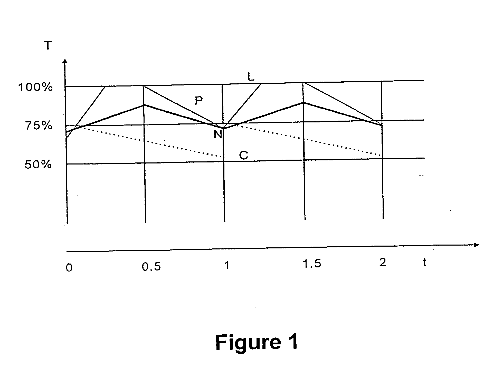
[0025]FIG. 1 is a coordinate graph for showing the main-spring tension variation for different clocks / watches. The abscissa represents time (t), the unit is (day). The ordinate represents tension (T) in percent, the horizontal line (L) represents fully wound (100%) of any main-spring. The dotted line (C) represents the tension variation of the main-spring of a chronometer (clock). Typically, the captain winds the chronometer (or clock) once every day to a spring tension of, say, 75%; after the clock runs 24 hours, the tension is reduced to 50%. Then the captain is rewound to 75%. Line (C) accordingly has a shape of saw-teeth. For accurate timing, any main-spring is never permitted to be fully wound. Therefore, we can see in FIG. 1 that the dotted line (C) will never touch the horizontal line (L).

[0026] In FIG. 1, the thin solid line (P) represents the tension variation of the main-spring of a self-winding watch wound by representative prior art apparatus in a watch shop under typic...


PUM


Abstract

A watch winder can automatically wind numerous kind/brand of self-winding watch and maintains the main-spring in ideal tension range. The watch in winding can always be positioned in its favorable showing orientation. The watch in winding can be mounted or dismounted easily. The noise produced by the winder is reduced significantly to a low level. The winder comprises a rotary bowl with central rectangular recess for receiving a cushion holder inserted on the bowl. An electrical noise-proof motor-gear system drives the rotary bowl. An IC circuitry installed under the panel controls the rotation mode of the motor-gear system. A length-wise retractile cushion holder is inserted in the recess with its width tightly fitted for carrying the watch in place. A switch means is installed on the panel with an indicating means for selecting a respective mode to drive the rotary base.

Description

FIELD OF THE INVENTION [0001] This invention relates to self-winding watches, particularly to an automatic watch-winding apparatus for keeping a self-winding watch wound during periods of non-use. BACKGROUND OF THE INVENTION [0002] Mechanical wrist watches employ spring wound mechanisms which convert the stored energy of the main-spring into mechanical movement of the watch's hands. Typically, such watches must be hand wound every two or three days to assure continuous operation. If the user forgets to wind the watch, the spring motor will eventually unwind causing the watch to cease operation. Self-winding mechanisms now commonly used in wrist watches are derived from technology dating to the 1930's. Such mechanisms comprise a rotary pendulum in the form of a sector with a swing angle of 120°. The inventive apparatus of this invention is designed for winding such self-winding mechanisms. [0003] Self-winding apparatus has been widely used by watch retailers and watch collectors. How...

Claims


Application Information

Patent Timeline
IPC IPC(8): G04C1/00G04B3/00G04B5/00G04BG04D7/00
CPCG04D7/009G04B3/006
Inventor LOUIE, LIP MAN
Owner HERO TEAM CORP
Why Eureka
Try Eureka