
Apparatus and method for transmitting/receiving pilot signals in a communication system using an orthogonal frequency division multiplexing scheme

Active Publication Date: 2006-01-26
SAMSUNG ELECTRONICS CO LTD
View PDF10 Cites 66 Cited by
  • Summary
  • Abstract
  • Description
  • Claims
  • Application Information

AI Technical Summary

Benefits of technology

[0032] To achieve the above and other objects, there is provided a method for providing a pilot symbol for base station identification in a Multiple-Input Mulitple-Output (MIMO) communication system having one or more transmission antennas, wherein the pilot symbol is comprised of a first sequence having a good cell identification characteristic and a second sequence for reducing a peak-to-average power ratio (PAPR) for all of pilot symbols.

Problems solved by technology

The use of the broadband spectrum resources considerably increases a fading effect in a wireless transmission path due to multipath propagation and causes a frequency-selective fading effect in the transmission frequency band.
However, the OFDM communication system should take the coherence bandwidth and the coherence time into consideration when transmitting pilot subcarrier signals in a time-frequency domain, and the pilot patterns having different slopes and different start points, generated taking into consideration the coherence bandwidth and the coherence time, are limited.
In this case, it is impossible to identify base stations using the pilot patterns.
Because generation of the pilot patterns used for identifying base stations included in the OFDM communication system is limited by the coherence bandwidth and the coherence time, the possible number of pilot patterns is also limited.
If the number of base stations included in the OFDM communication system increases, the number of distinguishable base stations is limited due to the limitation in the possible number of the pilot patterns.

Method used


Image

  • Apparatus and method for transmitting/receiving pilot signals in a communication system using an orthogonal frequency division multiplexing scheme
  • Apparatus and method for transmitting/receiving pilot signals in a communication system using an orthogonal frequency division multiplexing scheme
  • Apparatus and method for transmitting/receiving pilot signals in a communication system using an orthogonal frequency division multiplexing scheme

Examples


Embodiment Construction

[0044] A preferred embodiment of the present invention will now be described in detail with reference to the annexed drawings. In the following description, a detailed description of known functions and configurations incorporated herein has been omitted for conciseness.

[0045] The present invention proposes a scheme for transmitting / receiving pilot signals for base station (BS) and sector identification through one or more antennas in a communication system using an Orthogonal Frequency Division Multiplexing (OFDM) scheme (“OFDM communication system”). In particular, the present invention proposes a scheme for transmitting / receiving, through one or more antennas, pilot signals with minimized interference therebetween securing the base station and sector identification in the OFDM communication system.

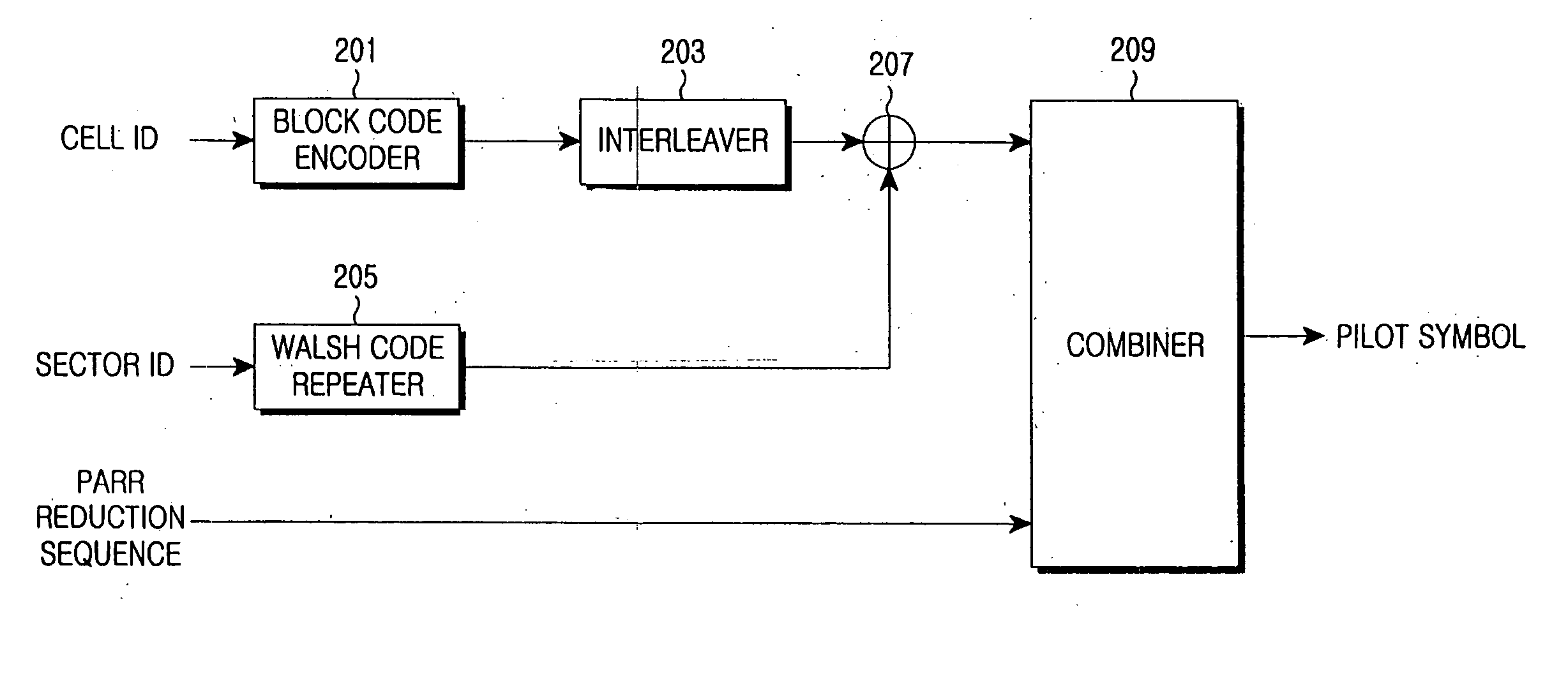
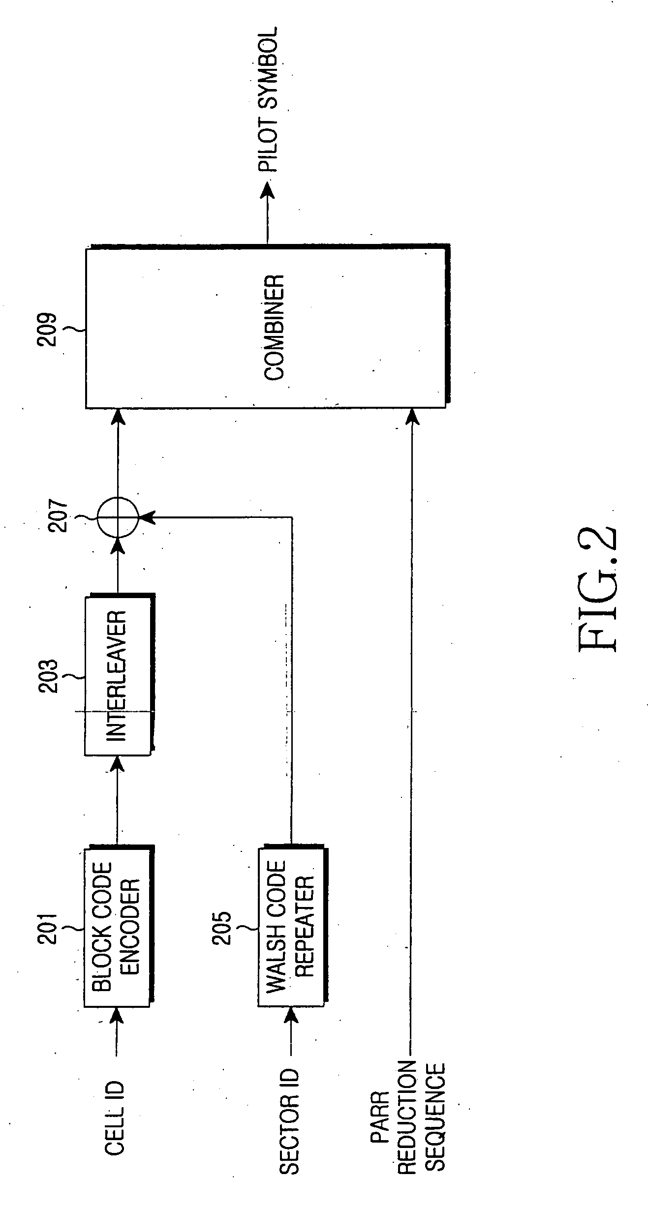
[0046]FIG. 2 is a diagram illustrating an internal structure of a pilot signal generator in an OFDM communication system according to an embodiment of the present invention. Referring...


PUM


Abstract

Disclosed is a method for providing a pilot symbol for base station identification in a Multiple-Input Multiple-Output (MIMO) communication system having one or more transmission antennas, wherein the pilot symbol is comprised of a first sequence having a good cell identification characteristic and a second sequence for reducing a peak-to-average power ratio (PAPR) for all of pilot symbols.

Description

PRIORITY [0001] This application claims priority under 35 U.S.C. § 119 to an application entitled “Apparatus and Method for Transmitting / Receiving Pilot Signals in a Communication System Using Orthogonal Frequency Division Multiplexing Scheme” filed in the Korean Intellectual Property Office on Jun. 25, 2004 and assigned Serial No. 2004-48249, and an application entitled “Apparatus and Method for Transmitting / Receiving Pilot Signals in a Communication System Using Orthogonal Frequency Division Multiplexing Scheme” filed in the Korean Intellectual Property Office on Aug. 26, 2004 and assigned Serial No. 2004-67648, the contents of both of which are incorporated herein by reference. BACKGROUND OF THE INVENTION [0002] 1. Field of the Invention [0003] The present invention relates generally to a communication system using an Orthogonal Frequency Division Multiplexing (OFDM) scheme, and in particular, to an apparatus and method for transmitting / receiving pilot signals used for distinguis...

Claims


Application Information

Patent Timeline
IPC IPC(8): H04J11/00H04J99/00H04L27/26
CPCH04L27/262H04L27/2613H04L1/0072H04L5/0048H04L5/0026H04L27/0008H04L27/20H04L27/362H04L27/26132H04J11/0069H04L1/0071H04J13/0048H04L1/0057
Inventor PARK, SUNG-EUNCHOI, SEUNG-HOONPARK, DONG-SEEKKIM, JAE-YOELJANG, JI-HOJOO, PAN-YUH
Owner SAMSUNG ELECTRONICS CO LTD
Features
  • Generate Ideas
  • Intellectual Property
  • Life Sciences
  • Materials
  • Tech Scout
  • Unparalleled Data Quality
  • Higher Quality Content
  • 60% Fewer Hallucinations
Learn More