Large-area individually addressable multi-beam x-ray system and method of forming same

a multi-beam x-ray, large-area technology, applied in the direction of nanoinformatics, nuclear engineering, tomography, etc., can solve the problems of limiting the size of scanners, and affecting the capture of clear images of moving parts

Inactive Publication Date: 2006-01-26
THE UNIV OF NORTH CAROLINA AT CHAPEL HILL
View PDF72 Cites 38 Cited by
  • Summary
  • Abstract
  • Description
  • Claims
  • Application Information

AI Technical Summary

Problems solved by technology

As a consequence of the current CT designs, the scanners are usually large with complicated mechanical systems.
Scanners can be limited by the rotation speed of the x-ray tube and by the size and weight of the apparatus.
This last limitation can adversely affect the capture of clear images of moving parts, such as a beating heart.
Although such a system is capable of producing dynamic 3D images, the scanner 200 is very large and costly to fabricate.
In addition to the design limitations of current CT scanners, current x-ray sources use heated metal filaments as the sources of electrons.
Because of the thermionic emission mechanism, a very high operating temperature is required, typically in the order of 1000-1500° C. The high operating temperatures results in problems such as short lifetime of the filament, slow response time (i.e., time to warm up the filament before emission), high-energy consumption, and large device size.
In x-ray tube applications, an additional electrical field can be applied to bring the electrons into focus at the target, but with attendant complexity and cost.
Additionally, such conventional techniques of focusing electron beams have certain disadvantages, such as limits on the uniformity and size of the focusing spots.

Method used


Image

  • Large-area individually addressable multi-beam x-ray system and method of forming same
  • Large-area individually addressable multi-beam x-ray system and method of forming same
  • Large-area individually addressable multi-beam x-ray system and method of forming same

Examples


Embodiment Construction

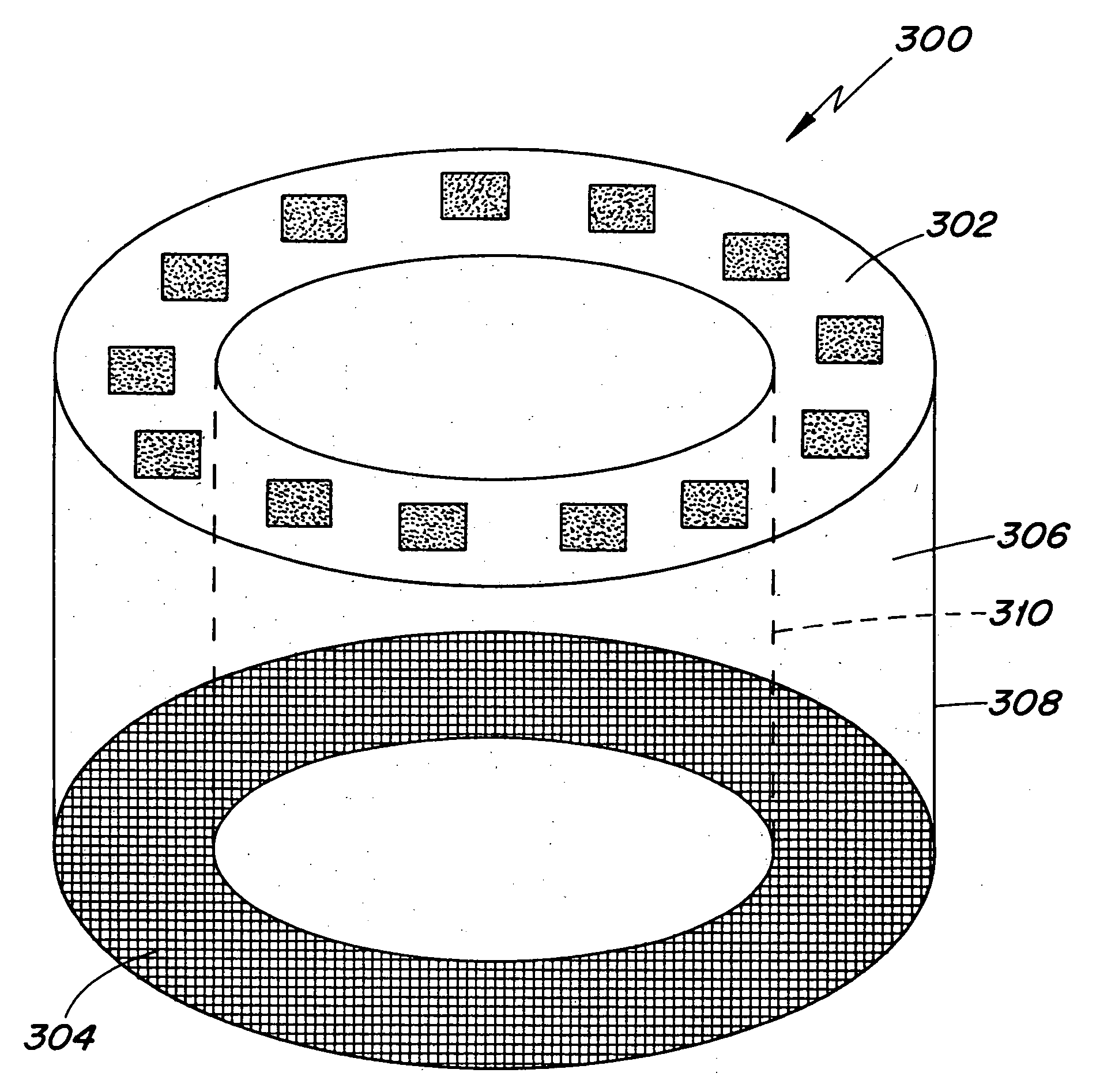
[0035] A structure to generate x-rays comprises a plurality of stationary and individually electrically addressable electron sources defining a plurality of cathodes, at least one target placed opposing the cathodes, and an evacuated chamber that houses the plurality of cathodes and the at least one target. The electron sources can be filed emission electron sources and can be triode-type or diode-type structures.

[0036]FIG. 3 is an embodiment of a structure 300 to generate x-rays. A cathode structure 302 and a target structure 304 are disposed within a chamber 306, which is substantially in the form of a hollow cylinder having an outer wall 308 and an inner wall 310. The cathode structure 302 and the anode structure 304 are positioned within the chamber 306 between the inner wall 308 and the outer wall 310. The chamber 306 is operationally maintained at a vacuum of at least 1 Torr by a suitable vacuum system operatively connected to the chamber 306. Feedthroughs (not shown), as kno...


PUM


Abstract

A structure to generate x-rays has a plurality of stationary and individually electrically addressable field emissive electron sources with a substrate composed of a field emissive material, such as carbon nanotubes. Electrically switching the field emissive electron sources at a predetermined frequency field emits electrons in a programmable sequence toward an incidence point on a target. The generated x-rays correspond in frequency and in position to that of the field emissive electron source. The large-area target and array or matrix of emitters can image objects from different positions and / or angles without moving the object or the structure and can produce a three dimensional image. The x-ray system is suitable for a variety of applications including industrial inspection / quality control, analytical instrumentation, security systems such as airport security inspection systems, and medical imaging, such as computed tomography.

Description

RELATED APPLICATION DATA [0001] This application is a continuation of U.S. patent application Ser. No. 10 / 051,183, filed on Jan. 22, 2002, which is a continuation-in-part of U.S. patent application Ser. No. 09 / 679,303, filed on Oct. 6, 2000, now U.S. Pat. No. 6,553,096. The entire disclosures of both referenced applications are incorporated herein by reference.STATEMENT REGARDING GOVERNMENT SUPPORT [0002] At least some aspects of this invention were made with Government support under contract no. N00014-98-1-05907. The Government may have certain rights in this invention.FIELD OF THE INVENTION [0003] The present invention relates to a method and device for generating and controlling x-ray radiation. For example, the present invention relates to a method and device that generates electron emission from an array or matrix of emitters. Emitted electrons directly impact different locations on a large-area target to produce multiple x-ray beams from different origins and thereby providin...

Claims


Application Information

Patent Timeline
Patent Type & Authority Applications(United States)
IPC IPC(8): H01J35/22H01J35/00H01J35/32A61B6/03A61B6/00G21K5/02G21K5/08H01J35/06H01J35/08H01J35/16H01J35/24H05G1/00H05G1/34
CPCA61B6/032A61B6/4028B82Y10/00H01J35/065H05G1/34H01J35/22H01J2201/30469H01J2235/064H01J2235/068H01J35/14H01J35/147
Inventor ZHOU, OTTO Z.LU, JIANPINGQIU, QI
Owner THE UNIV OF NORTH CAROLINA AT CHAPEL HILL
Why Eureka
Try Eureka