Vehicle automatic exterior light control

a technology of automatic exterior light control and headlamps, which is applied in the direction of vehicle headlamps, instruments, transportation and packaging, etc., can solve the problems of system that effectively detects headlights not being able to adequately detect taillights, most prior systems not being able to distinguish nuisance light sources, and system being subject to undesirable high beam dimming

Inactive Publication Date: 2006-01-26
STAM JOSEPH S +5
View PDF9 Cites 365 Cited by
  • Summary
  • Abstract
  • Description
  • Claims
  • Application Information

AI Technical Summary

Problems solved by technology

Some systems that effectively detect headlights are unable to adequately detect taillights.
Most prior systems are unable to distinguish nuisance light sources, such as reflectors, street signs, streetlights, house lights, or the like, from light sources that require headlight control.
Accordingly, these systems are subject to undesirable dimming of the high beams when no other traffic is present and turning on the high beams when other vehicles are present.
In addition to the undesirable performance, it is difficult for prior systems to comply with the legal requirements as described above for high beam control while avoiding unnecessary dimming of the vehicle headlamps.
Fog lights are examples of other vehicle lights that are difficult to control automatically.
A reliable method of automatically controlling such fog lights has not been available.

Method used


Image

  • Vehicle automatic exterior light control
  • Vehicle automatic exterior light control
  • Vehicle automatic exterior light control

Examples


Embodiment Construction

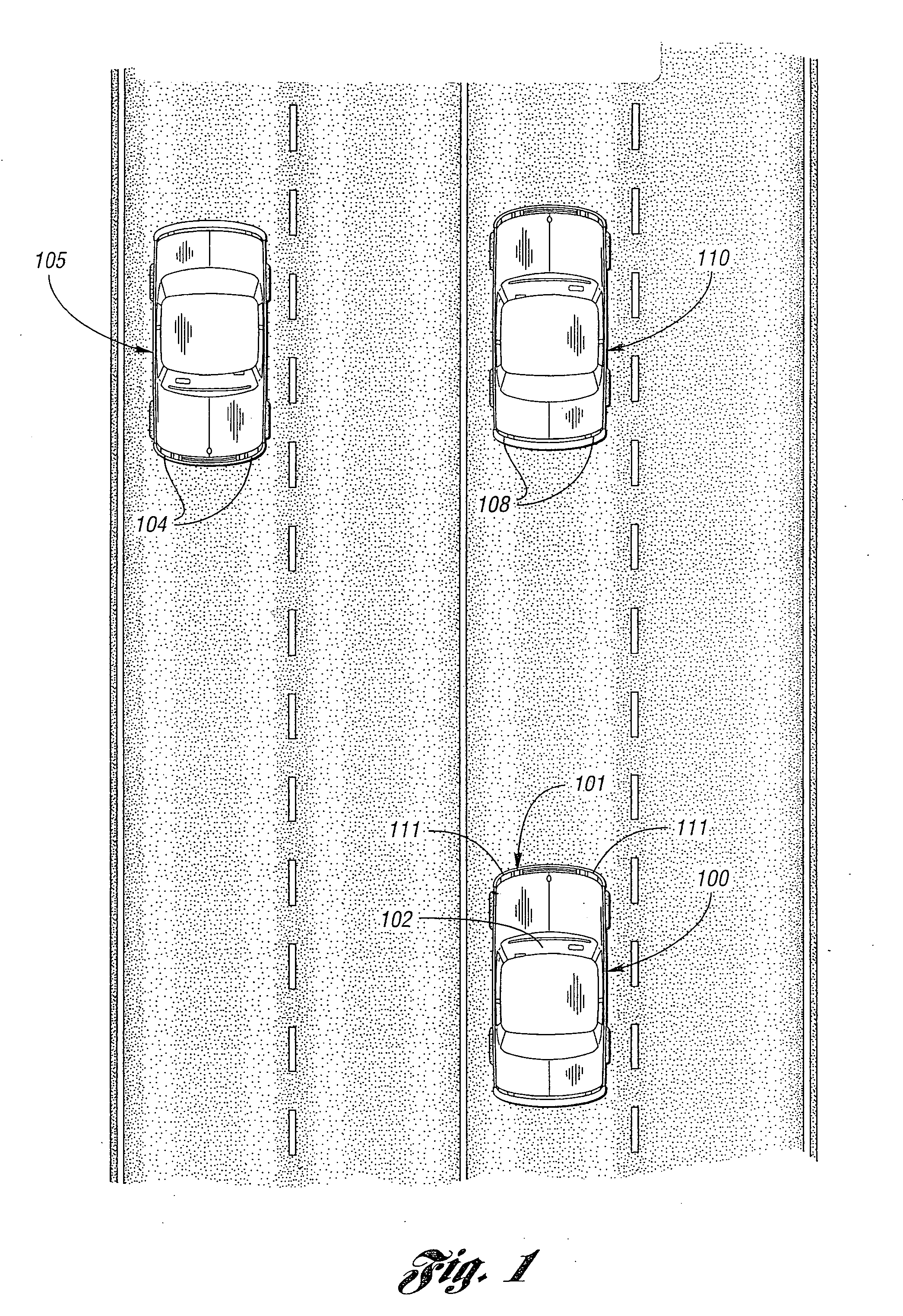
[0047] A controlled vehicle 100 (FIG. 1) having an automatic headlamp dimmer includes an optical sensor system 102 for detecting the headlamps 104 of an oncoming vehicle 105 and the taillights 108 of a preceding vehicle 10. The headlights 111 of the controlled vehicle 100 are controlled automatically to avoid shining the high beams, or bright lights, directly into the eyes of a driver of oncoming vehicle 105 or by reflection into the eyes of the driver of the preceding vehicle 110. The optical sensor assembly 102 is illustrated mounted in the windshield area of the vehicle, but those skilled in the art will recognize that the sensor could be mounted at other locations that provide the sensor with a view of the scene in front of the vehicle. One particularly advantageous mounting location is high on the vehicle windshield to provide a clear view, which view can be achieved by mounting the optical sensor assembly 102 in a rearview mirror mount, a vehicle headliner, a visor, or in an o...


PUM


Abstract

A system and method of automatically controlling vehicle exterior lights including an image sensor and a controller to generate headlamp control signals.

Description

CROSS-REFERENCE TO RELATED APPLICATIONS [0001] This application is a continuation of U.S. patent application Ser. No. 10 / 326,673, filed Dec. 19, 2002, by Joseph S. Stam et al. entitled “VEHICLE LAMP CONTROL,” which is a continuation of U.S. patent application Ser. No. 09 / 528,389 filed Mar. 20, 2000, by Joseph S. Stam et al. entitled “VEHICLE LAMP CONTROL,” now U.S. Pat. No. 6,611,610, which is a continuation-in-part of U.S. patent application Ser. No. 09 / 151,487 entitled “CONTROL SYSTEM TO AUTOMATICALLY DIM VEHICLE HEAD LAMPS,” filed on Sep. 11, 1998, by Joseph S. Stam et al., now U.S. Pat. No. 6,255,639, which is a continuation of U.S. Pat. No. 5,837,994, entitled “CONTROL SYSTEM TO AUTOMATICALLY DIM VEHICLE HEAD LAMPS,” filed on Apr. 2, 1997, by Joseph S. Stam et al., the entire disclosures of which are incorporated herein by reference. Priority under 35 U.S.C. § 120 is hereby claimed on the above-identified patent applications.FIELD OF THE INVENTION [0002] The present invention p...

Claims


Application Information

Patent Timeline
Patent Type & Authority Applications(United States)
IPC IPC(8): G06K9/00B60Q1/08B60Q1/14B60Q1/18G06V10/141
CPCB60Q1/085G06K9/00825B60Q1/18B60Q2300/054B60Q2300/056B60Q2300/112B60Q2300/114B60Q2300/116B60Q2300/122B60Q2300/134B60Q2300/142B60Q2300/144B60Q2300/21B60Q2300/312B60Q2300/314B60Q2300/32B60Q2300/322B60Q2300/332B60Q2300/3321B60Q2300/333B60Q2300/334B60Q2300/337B60Q2300/41B60Q2300/42B60Q2400/30G06K9/00664G06K9/2027B60Q1/143G06V20/10G06V20/584G06V10/141
Inventor STAM, JOSEPH S.BECHTEL, JON H.REESE, SPENCER D.ROBERTS, JOHN K.TONAR, WILLIAM L.POE, G. BRUCE
Owner STAM JOSEPH S
Why Eureka
Try Eureka