
Stereo vehicle-exterior monitoring apparatus

a monitoring apparatus and vehicle technology, applied in the direction of instruments, using reradiation, transportation and packaging, etc., can solve the problems of inability to recognize a subject outside the range, narrow monitoring range obtained during night driving, and difficulty in obtaining a monitored range similar to that of daytime driving. , to achieve the effect of increasing the monitored area and enhancing the monitoring accuracy

Inactive Publication Date: 2006-01-26
SUBARU CORP
View PDF9 Cites 32 Cited by
  • Summary
  • Abstract
  • Description
  • Claims
  • Application Information

AI Technical Summary

Benefits of technology

The present invention provides a stereo vehicle-exterior monitoring apparatus that can achieve a wider monitored range even during night driving for higher accuracy of monitoring. The apparatus includes a floodlight lamp, multiple infrared auxiliary lights, stereo cameras, and a stereo image processing portion. The infrared auxiliary lights light up a more distant place by infrared light than the floodlight lamp and a closer place and wider angle of lighting by infrared light than the floodlight lamp. The stereo cameras capture images of the infrared auxiliary lights and the surrounding of the vehicle. The stereo image processing portion calculates distance data based on the images and monitors a subject present in the surrounding of the vehicle. The apparatus can provide a wider range of monitored area and enhance accuracy of monitoring during night driving.

Problems solved by technology

An enlargement of a monitored area during night driving may be one of problems to be solved by a stereo outside monitoring apparatus mounted in a vehicle such as an automobile.
Under this lighting condition, the monitoring apparatus cannot recognize a subject present in a lighting range of the headlight but cannot recognize a subject outside of the range easily except that the subject itself emits light.
As a result, the monitored range obtained during night driving is inevitably narrower than that of daytime driving.
However, even in this case, obtaining a monitored range during night driving similar to that of daytime driving is still difficult.
In other words, the same problem still exists even with, for example, the infrared auxiliary light in addition to the backlight when the rear part of the vehicle is monitored.

Method used


Image

  • Stereo vehicle-exterior monitoring apparatus
  • Stereo vehicle-exterior monitoring apparatus
  • Stereo vehicle-exterior monitoring apparatus

Examples


Embodiment Construction

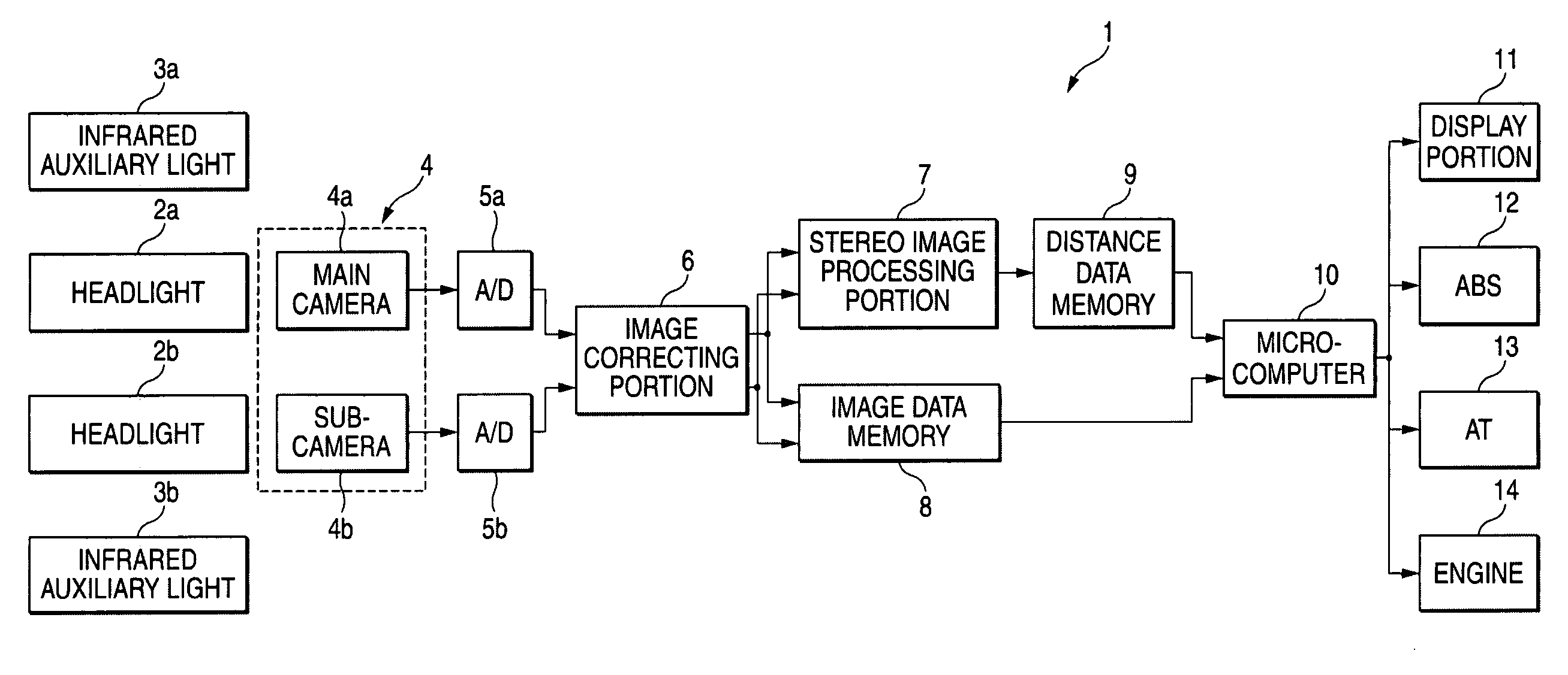
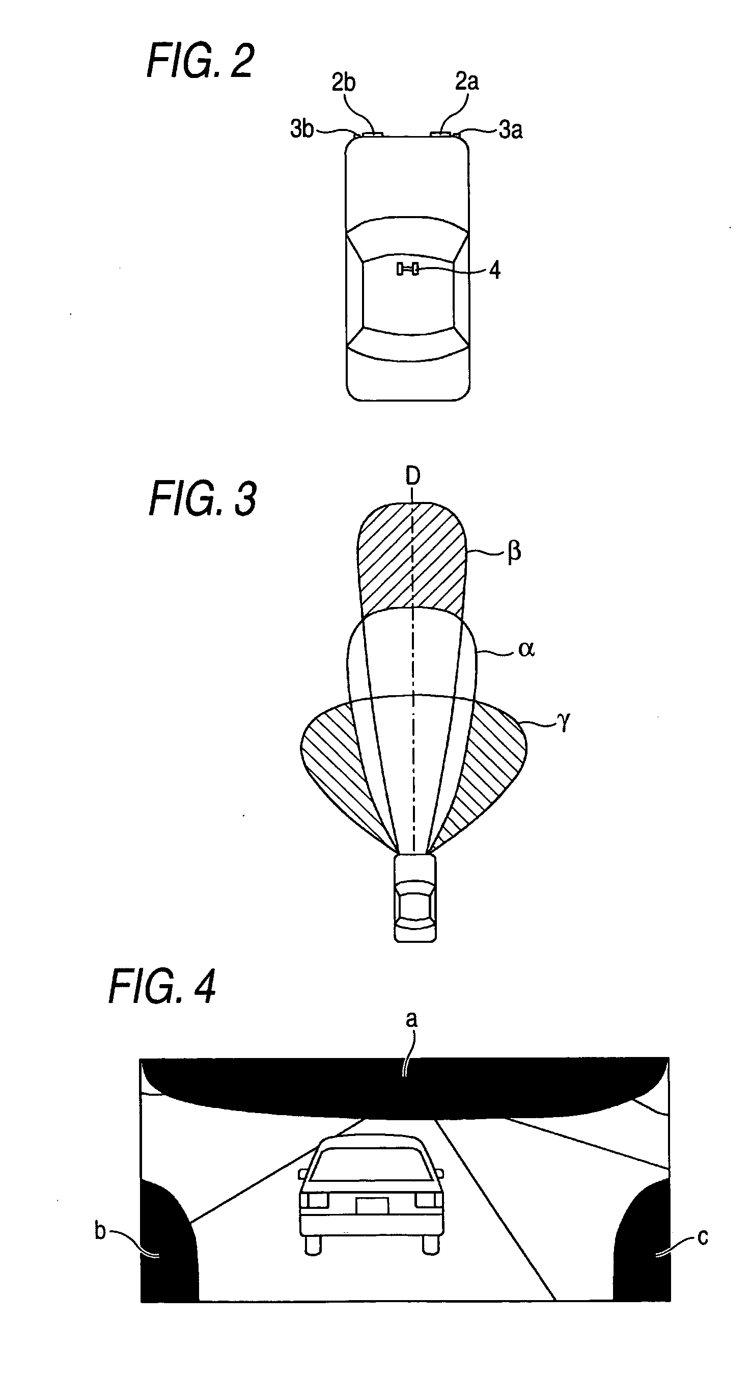
[0021]FIG. 1 is a block construction diagram of a stereo vehicle-exterior monitoring apparatus according to an embodiment. A stereo vehicle-exterior monitoring apparatus 1 therein obtains a wider monitored area for monitoring control than the monitored area with a headlight only by operating a headlight and an infrared auxiliary light cooperatively during night driving (that is, during driving under an extremely dark circumstance) when the visibility of the front part of the vehicle thereof is low. As shown in FIG. 2, headlights 2a and 2b serving as floodlight lamps are separately mounted at the left and right of the front part of the vehicle and irradiate visible light to the front part of the vehicle. One infrared auxiliary light 3a is provided near one headlight 2a mounted at the front right part of the vehicle, for example. The other infrared auxiliary light 3b is mounted near the other headlight 2b mounted at the front left part of the vehicle, for example. These infrared auxil...


PUM


Abstract

A stereo vehicle-exterior monitoring apparatus includes a stereo camera including a pair of infrared cameras and floodlight lamp and infrared lights. The Infrared lights light up a more distant place than that is lighted up by the floodlight lamp, or light up a closer place and wider angle of lighting than that is lighted up by the floodlight lamp so as to obtain a wider monitored area than that with the lighting by the floodlight lamp. The stereo camera shoots at least lighting ranges of the infrared lights for obtaining a distance data of subject present in the surrounding of the vehicle.

Description

CROSS REFERENCE TO RELATED APPLICATIONS [0001] The disclosure of Japanese Application No. 2004-175198 filed on Jun. 14, 2004 including the specification, drawings and abstract is incorporated herein by reference in its entirety. BACKGROUND OF THE INVENTION [0002] 1. Field of the Invention [0003] The present invention relates to a stereo vehicle-exterior monitoring apparatus that monitors the surrounding of a vehicle thereof by using stereo cameras including a pair of infrared cameras. [0004] 2. Description of the Related Art [0005] For example, Japanese Patent Publication JP-A-2001-344597 discloses a stereo monitoring apparatus having a pair of infrared cameras in order to achieve higher monitoring accuracy during night flight of an airplane. Japanese Patent Publication JP-A-2003-217319 discloses a night-vision equipment that provides a night vision of the front part of a vehicle thereof lighted by a monocular infrared camera with both visible light and infrared light. The night-vis...

Claims


Application Information

Patent Timeline
Patent Type & Authority Applications(United States)
IPC IPC(8): G06K9/00B60R1/00B60Q1/24B60W40/02G08G1/16H04N7/18
CPCB60R1/00B60R2300/103B60R2300/105B60R2300/106G01S17/46B60R2300/30B60R2300/8053B60W40/02G01S11/12B60R2300/107
Inventor SOGAWA, YOSHIYUKI
Owner SUBARU CORP
Learn More