Imprint alignment method, system, and template

a technology of imprint alignment and template, applied in the field of imprint alignment method, system, and template, can solve the problems of inability to properly align the subsequent imprint lithography device layer, and inability to meet the needs of use, and achieve the effect of partial utility

Inactive Publication Date: 2006-01-26
CANON KK
View PDF68 Cites 75 Cited by
  • Summary
  • Abstract
  • Description
  • Claims
  • Application Information

AI Technical Summary

Benefits of technology

[0009] Presented herein is an improved alignment method with particular utility in imprint lithography applications. In an embodiment, the method of improving lithographic alignment essentially comprises imprinting a first layer on a substrate and imprinting a second layer on the first layer, the first layer including an array of first-layer geometries each arranged within a respective subfield with each first-layer geometry including at least one first-layer feature, and the second layer including an array of second-layer geometries each arranged within a respective subfield with each second-layer geometry including at least one second-layer feature, where at least one second-layer feature has at least one corresponding first-layer feature, where at least one second-layer geometry has a corresponding first-layer geometry, and where at least one second-layer geometry is intentionally offset from its corresponding first-layer geometry. In an embodiment, at least two second-layer geometries are intentionally offset from their corresponding first layer geometries, and said offsets are not equal.

Problems solved by technology

In the extreme, lithographic misalignment may lead to shorting between structures that should be isolated from each other, and isolation of structures that should be coupled to each other.
Properly aligning subsequent imprint lithography device layers becomes increasingly difficult as feature sizes become ever smaller.
Despite a high degree of alignment accuracy, current imprint lithography systems are challenged by the degree of precision required to consistently align multiple layers having minimum feature sizes.
Consequently, proper alignment of multi-layered devices having minimum feature sizes may be a relatively infrequent event.

Method used


Image

  • Imprint alignment method, system, and template
  • Imprint alignment method, system, and template
  • Imprint alignment method, system, and template

Examples


Embodiment Construction

[0019] Although an imprint lithography system may have a high degree of alignment accuracy, the alignment precision may not suffice for multi-layered devices having sub 100 nm features. Using typical lithography methods, systems, and devices, a system having a three sigma alignment accuracy of less than about 500 nm may not be sufficient to produce functional, multi-layered devices having, for example, registration tolerances of about 25 nm or less, and having minimum feature sizes of, for example, about 50 nm or less. An exemplary lithographic system is available under the trade name IMPRIO 100™ from Molecular Imprints, Inc. having a place of business at 1807-C Braker Lane, Suite 100, Austin, Tex. 78758. The system description for the IMPRIO 100™ is available at www.molecularimprints.com and is incorporated herein by reference.

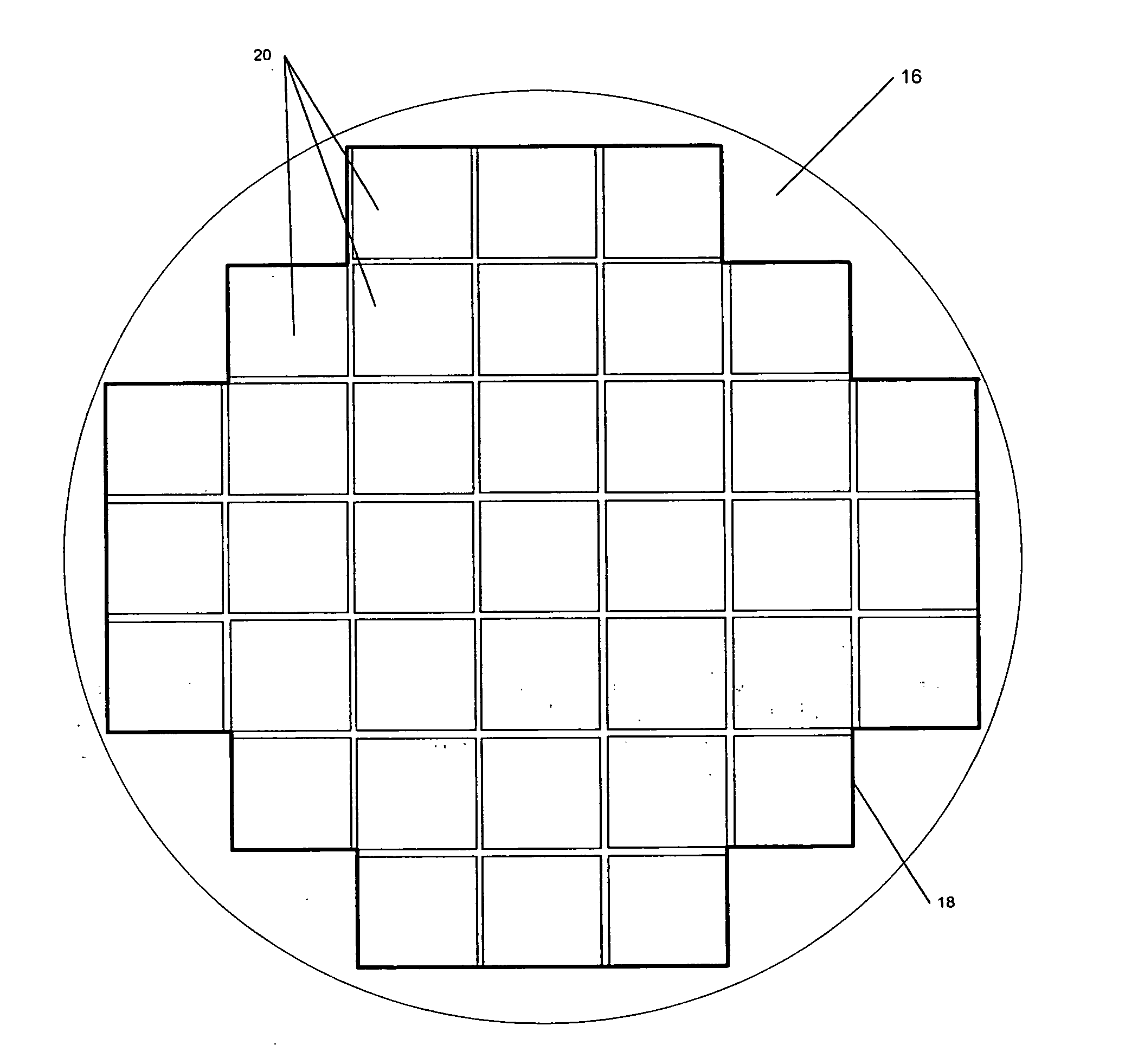
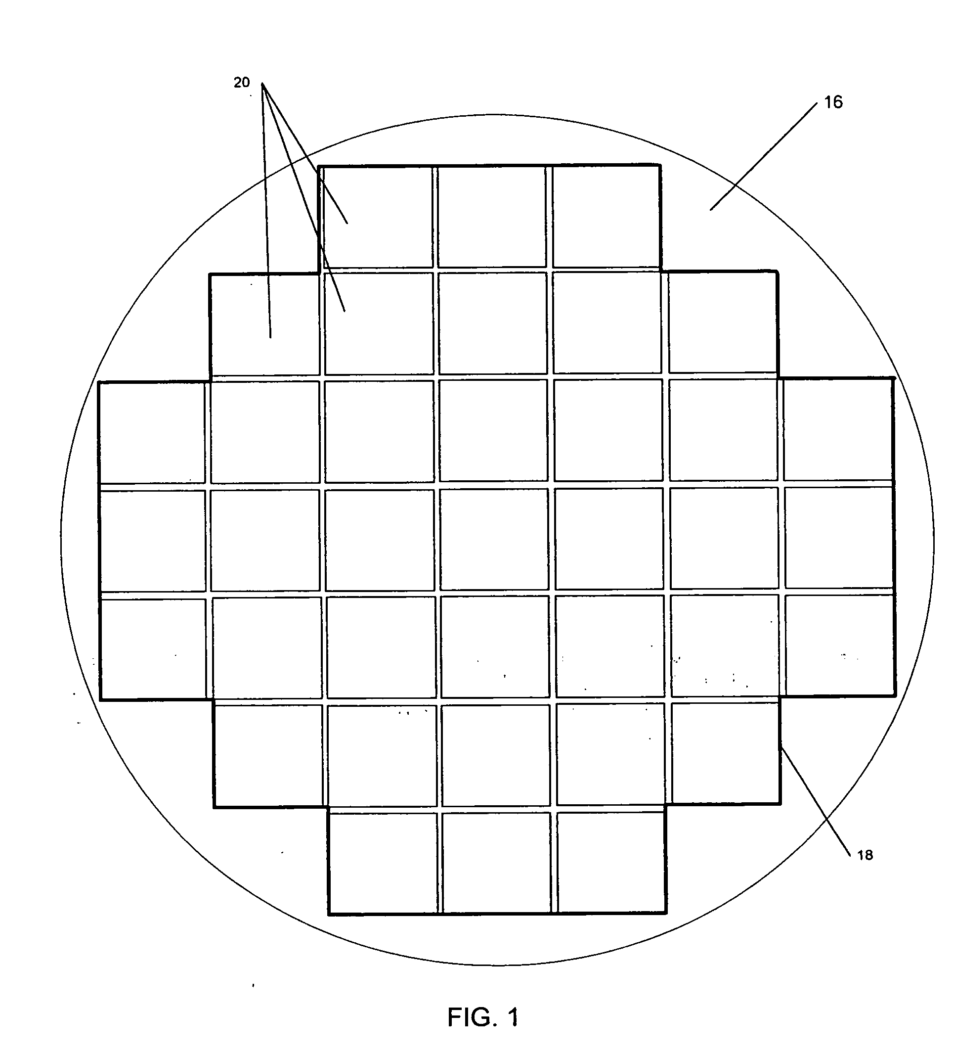
[0020] Typically all the layers within a respective print field are replicated substantially identically, resulting in substantially identical devices withi...


PUM

PropertyMeasurementUnit
feature sizesaaaaaaaaaa
sizeaaaaaaaaaa
sizesaaaaaaaaaa

Abstract

An improved lithographic alignment method, system, and template. The method includes creating, within a lithographic subfield, subsequent-layer features which are intentionally offset from their respective previous-layer features, where the intentional offset may vary in magnitude and direction from one subfield to the next. The system includes an imprint lithographic machine and first and second lithography templates where the templates are adapted to enable the machine to form first and second features, respectively, and where a second feature is configured to be deliberately offset from a corresponding first feature. The template set includes at least two templates, one having features which are deliberately offset from corresponding features of another template. Also, a method of manufacturing such a template set.

Description

BACKGROUND OF THE INVENTION [0001] 1. Field of the Invention [0002] The present invention relates to a method of improving imprint lithography alignment as well as a system and template to be used for same. The method, system, and template herein described have particular utility in subfield alignment of sub 100 nm features requiring registration of about 25 nm. [0003] 2. Description of the Related Art [0004] Micro-fabrication involves the fabrication of very small structures, e.g., having features on the order of micrometers or smaller. One industry that has been driving the fabrication of increasingly smaller structures is the electronics industry. As electronic devices have become smaller and faster, the integrated circuits that drive them have necessarily become smaller. [0005] A technique known as ‘photolithography’, or simply ‘lithography’, is typically employed in the manufacture of integrated circuits. Lithographic techniques are generally used to pattern the various levels ...

Claims


Application Information

Patent Timeline
Patent Type & Authority Applications(United States)
IPC IPC(8): G03F9/00G03C5/00G03F1/00B28B17/00B28B11/08A01J21/00B29B13/00B29C59/00A01J25/12
CPCG03F7/70633G03F7/7035Y10S977/887
Inventor VOISIN, RONALD D.
Owner CANON KK
Why Eureka
Try Eureka