Control device of high-pressure fuel system of internal combustion engine

Active Publication Date: 2006-02-02
TOYOTA JIDOSHA KK
View PDF9 Cites 26 Cited by
  • Summary
  • Abstract
  • Description
  • Claims
  • Application Information

AI Technical Summary

Benefits of technology

[0015] According to this invention, the amount of the fuel required to be discharged from the high-pressure fuel pumps is detected by calculation based on a required fuel injection amount and fluctuation in fuel pressure. The high-pressure fuel pumps, increasing the fuel pressure to about 13 MPa, will cause noise and vibration. Thus, during idling or the like where the load of the internal combustion engine is small, the discharge ratio determination portion determines the fuel discharge ratio among the plurality of high-pressure fuel pumps so as to activate the minimum number of high-pressure fuel pumps required. This can improve the overall efficiency of the high-pressure fuel system formed of the high-pressure fuel pumps since unnecessary pumps are not activated. This also ensures that each high-pressure fuel pump is activated at a proper load, since the fuel discharge ratio among the high-pressure fuel pumps can be determined as appropriate. Accordingly, reliability of the high-pressure fuel pumps can be increased. Furthermore, even in the case where the high-pressure fuel pumps have different characteristics (different discharge amounts), overall control of the pumps is possible, so that the high-pressure fuel system of a high level of safety can be implemented. As a result, it is possible to provide a control device of a high-pressure fuel system of an internal combustion engine having a plurality of high-pressure fuel pumps that can control the high-pressure fuel pumps in a cooperative manner.
[0019] According to this invention, the high-pressure fuel pumps are controlled using the drive duties. This ensures highly accurate control of the fuel discharge ratio among the high-pressure fuel pumps as well as the fuel discharge amounts of the high-pressure fuel pumps. Accordingly, the combustion state of the fuel in the internal combustion engine can be controlled appropriately, and thus, fuel efficiency, exhaust emission, and drivability can be maintained at favorable states.
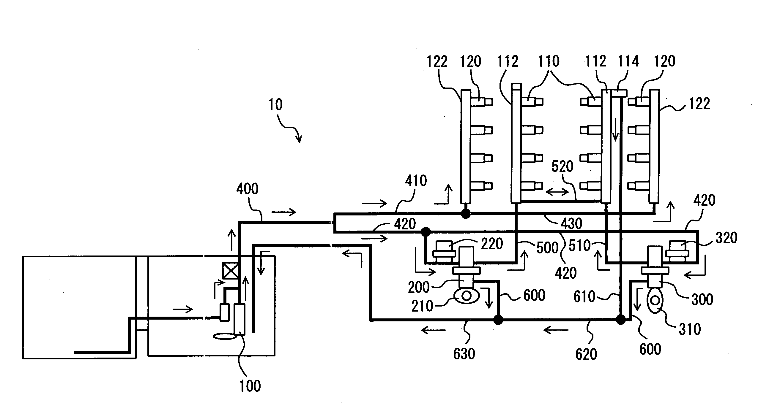
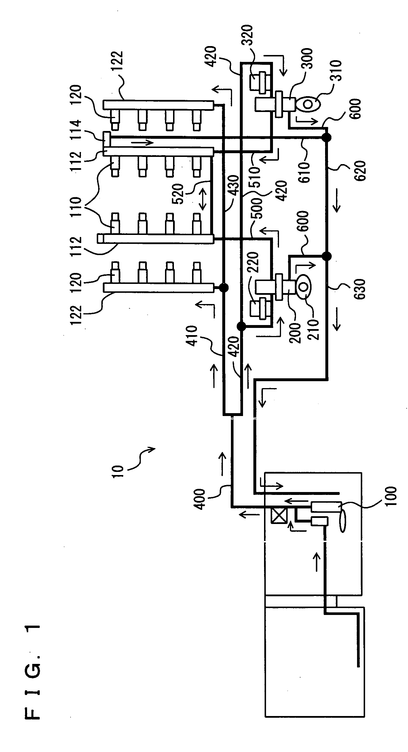
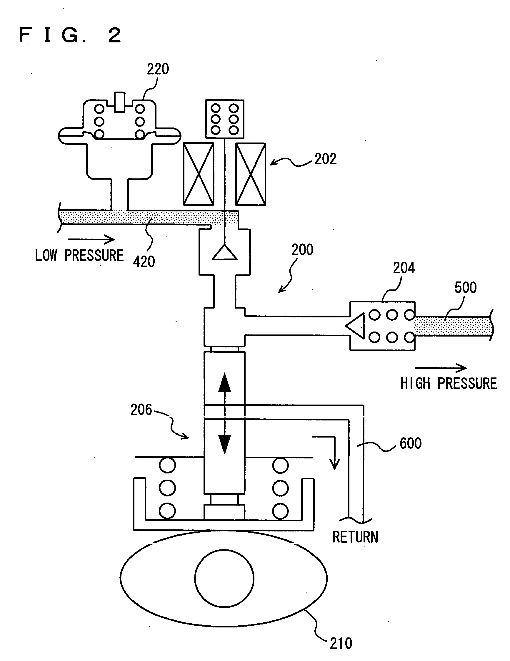
[0021] According to this invention, in order to suppress fuel leakage from the fuel injection mechanism while the internal combustion engine is stopped, the high-pressure fuel in the high-pressure fuel system is returned to the fuel tank by the relief function (leakage function) provided to the check valve arranged between the high-pressure fuel pump and the high-pressure delivery pipe, for example. (As an example of the relief function, the check valve is provided with pores that remain always open, through which the high-pressure fuel flows toward the fuel tank upon occurrence of a pressure difference when the high-pressure fuel pump is not activated). The (relieved) amount of the fuel because of this relief function is taken into account when calculating the amount of the fuel required to be discharged from the high-pressure fuel pumps, ensuring accurate calculation thereof
[0023] According to this invention, it is determined whether at least one high-pressure fuel pump can be stopped, based on the overall discharge amount of the high-pressure fuel pumps and the required discharge amount thereof. At this time, since the (relived) amount of the fuel because of the relief function is taken into account, overload corresponding to the relieved amount of the fuel will not be imposed on the pump other than the one from which discharge is stopped. This can improve reliability of the entire high-pressure fuel system.
[0026] According to this invention, it is possible to make the plurality of high-pressure fuel pumps discharge the fuel in approximately equal amount. This can prevent pulsation sound due to fluctuation in discharge pulsation, and steady pulsation sound is ensured. As such, abnormal noise due to the pulsation can be reduced. Further, variation in injection amount due to the pulsation can also be suppressed.
[0030] According to this invention, it is possible to determine faulty pumps from among the plurality of high-pressure fuel pumps in a simple manner, by activating the high-pressure fuel pumps one by one by a predetermined drive duty.

Problems solved by technology

The high-pressure fuel pumps, increasing the fuel pressure to about 13 MPa, will cause noise and vibration.

Method used


Image

  • Control device of high-pressure fuel system of internal combustion engine
  • Control device of high-pressure fuel system of internal combustion engine
  • Control device of high-pressure fuel system of internal combustion engine

Examples


Embodiment Construction

[0037] Hereinafter, embodiments of the present invention will be described with reference to the drawings. In the following description, the same reference characters denote the same portions having the same names and functions. Thus detailed description thereof will not be repeated.

[0038]FIG. 1 shows a fuel supply system 10 of an engine controlled by an engine ECU (Electronic Control Unit) that is a control device according to an embodiment of the present invention. The engine is a V-type 8-cylinder gasoline engine, and has in-cylinder injectors 110 for injecting the fuel into the respective cylinders, and intake manifold injectors 120 for injecting the fuel into intake manifolds of the respective cylinders. It is noted that the present invention is not applied exclusively to such an engine, but is also applicable to a gasoline engine of another type and a common rail diesel engine. Further, the number of high-pressure fuel pumps is not restricted to two, but may be any number of ...


PUM


Abstract

An engine ECU performs a program including the steps of calculating an amount of the fuel required to be discharged from high-pressure fuel pumps (the required discharge amount), determining whether one high-pressure fuel pump can be stopped, and if not, determining whether the required discharge amount exceeds a maximum possible discharge amount of one high-pressure fuel pump of smaller capability, and if not, causing the two high-pressure fuel pumps to discharge the fuel in approximately equal amount, or if so, causing the high-pressure fuel pump of smaller capability to discharge the fuel of the maximum possible discharge amount and causing the high-pressure fuel pump of larger capability to discharge the fuel of the amount obtained by subtracting the discharge amount of the high-pressure fuel pump of smaller capability from the required discharge amount.

Description

[0001] This nonprovisional application is based on Japanese Patent Application No. 2004-222773 filed with the Japan Patent Office on Jul. 30, 2004, the entire contents of which are hereby incorporated by reference. BACKGROUND OF THE INVENTION [0002] 1. Field of the Invention [0003] The present invention relates to a control device of a high-pressure fuel system of an internal combustion engine that includes fuel injection means (in-cylinder injector) for injecting a fuel into a cylinder at a high pressure, or an internal combustion engine that includes, in addition to the above fuel injection means, fuel injection means (intake manifold injector) for injecting a fuel into an intake manifold or an intake port. More particularly, the present invention relates to a technique for controlling a high-pressure fuel system having a plurality of high-pressure fuel pumps. [0004] 2. Description of the Background Art [0005] An engine having a first fuel injection valve (in-cylinder injector) fo...

Claims


Application Information

Patent Timeline
IPC IPC(8): F02M57/02F02D41/30F02D41/38F02M63/02
CPCF02D41/3094F02D41/3845F02D2041/3881F02D2250/31F02D41/3082F02M63/0225F02M63/029F02M69/046F02D41/221F02M59/366F02D41/123
Inventor NOMURA, MITSUHIRO
Owner TOYOTA JIDOSHA KK
Why Eureka
Try Eureka