
Recording apparatus

Inactive Publication Date: 2006-02-02
CANON KK
View PDF19 Cites 16 Cited by
  • Summary
  • Abstract
  • Description
  • Claims
  • Application Information

AI Technical Summary

Benefits of technology

[0006] The primary object of the present invention is to provide a recording apparatus in which the ink, paper dust, etc., on its recording medium conveyance roller(s) are removed to minimize the amount of the contamination of a recording medium attributable to the transfer of the abovementioned foreign substances onto the recording medium.

Problems solved by technology

However, the above described recording apparatuses, in particular, ink jet recording apparatuses, which record images on a recording medium by ejecting minuscule ink droplets from ink ejection orifices, have the following technical problems to be solved.
In particular, when an image is recorded in the border-less fashion, some ink droplets fly into the space outward of the edges of the recording medium, being therefore likely to turn into the ink mist, because of the distance between the edge of the recording medium to a waste ink absorbing member located on the bottom side of the platen.
If one of these portions happens to be the peripheral surface of a recording medium conveyance roller, which comes into contact with recording medium, the ink (ink mist) having adhered thereto is transferred onto a recording medium, resulting in the formation of low quality images.
This type of contamination of recording medium is considerably more inconvenient when printing on both sides of a recording paper.
There is another problem common to various recording apparatuses different in terms of recording method.
This problem is that paper dust sometimes adheres to recording medium conveyance roller(s).
Thus, as the cumulative hours of the usage of a recording apparatus increases, the amount of the paper dust on the peripheral surface of the conveyance roller(s) becomes substantial, reducing the conveyance roller(s) in conveyance performance, which sometimes results in the formation of images of inferior quality.

Method used


Image

  • Recording apparatus
  • Recording apparatus
  • Recording apparatus

Examples


Embodiment Construction

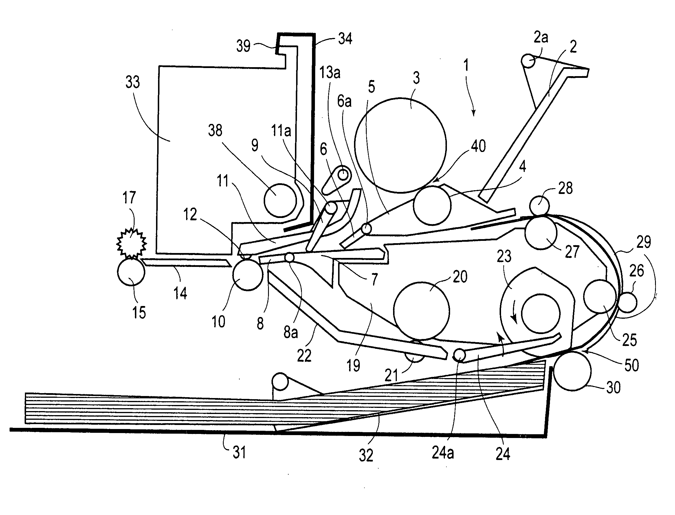
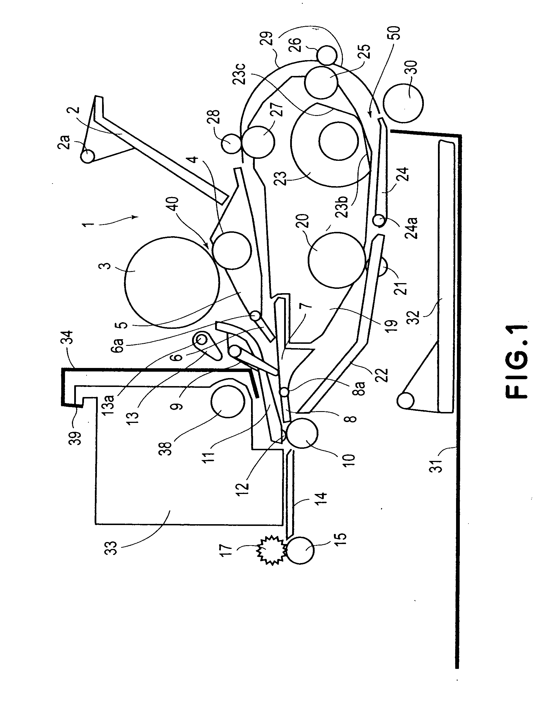
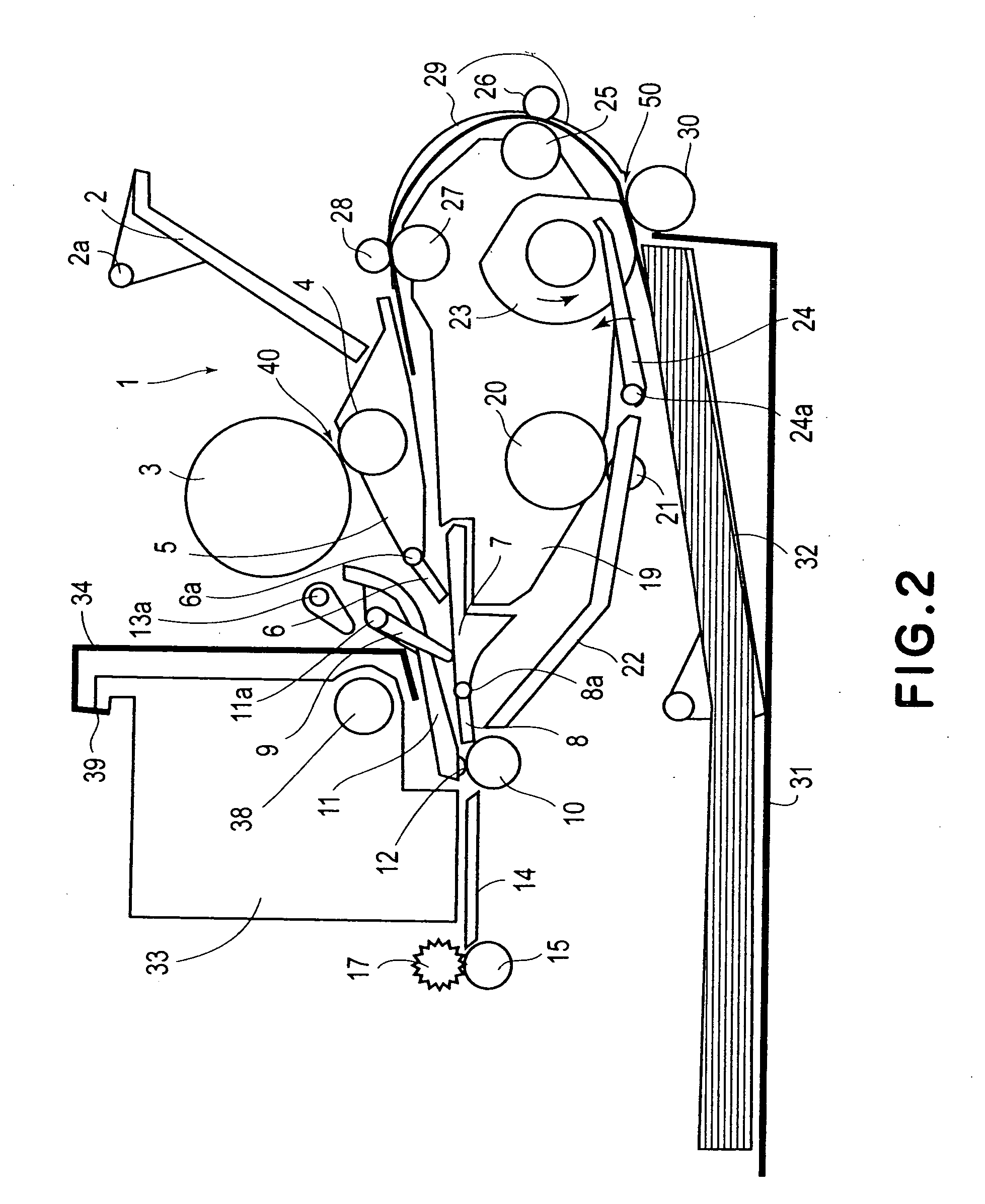
[0018] Hereinafter, one of the preferred embodiments of the present invention will be described in more detail with reference to the appended drawings. Throughout the following description of the preferred embodiment, if a component in a drawing is identical in referential symbol to a component in another drawing, the two components are virtually identical in function. FIG. 1 is a sectional view of the recording apparatus in an example of the preferred embodiment of the present invention. The recording apparatus in this embodiment is provided with two type of sheet conveying mechanisms, that is, an ASF (automatic Sheet Feeder) located on top of the main assembly, and an ASF which is located in the bottom portion of the main assembly and feeds recording sheets through the U-turn portion of the two-sided printing path, and a mechanism for automatically switching the recording medium path between the single-sided printing path and two-sided printing path. In FIG. 1, a referential symbo...


PUM


Abstract

A recording apparatus for effecting recording by a recording head on a recording material which is fed by a plurality of pairs of feeding rollers, the recording apparatus, includes a first feeding roller for feeding the recording material with a first feeding force; a second feeding roller for feeding the recording material with a second feeding force which is smaller than the first feeding force; control means for stopping the first feeding roller with a sheet material nipped to cause rubbing between the second feeding roller and the sheet material to effect cleaning to a peripheral surface of the second feeding roller.

Description

FIELD OF THE INVENTION AND RELATED ART [0001] The present invention relates to a recording apparatus which employs one or more recording heads to form an image on recording medium while the recording medium is conveyed by recording medium conveyance rollers. More specifically, it relates to a cleaning means for cleaning the abovementioned recording medium conveyance rollers of a recording apparatus. [0002] Recording apparatuses having the function of a printer, a copying apparatus, a facsimileing machine, and / or the like, recording apparatuses used as the outputting device for a multi-functional electronic device or workstation, which comprises a computer and / or wordprocessor, etc., are structured to form an image on recording media, such as a piece of paper or plastic sheet, according to image formation data. In recent years, digital cameras have come to be widely used. With the widespread usage of digital cameras, recording apparatuses have come to be widely used as a means for pr...

Claims


Application Information

Patent Timeline
IPC IPC(8): B41J2/01
CPCB41J13/02B41J3/60
Inventor NISHIBERI, NOZOMUUCHIDA, HARUOSAITO, HIROYUKIHAMANO, TETSU
Owner CANON KK
Learn More