Optical disk and information playback apparatus

a technology of information playback and optical disk, which is applied in the field of optical disk and information playback apparatus, can solve the problems of signal leakage from another layer becoming a noise source in recording information

Inactive Publication Date: 2006-02-02
KK TOSHIBA
View PDF4 Cites 16 Cited by
  • Summary
  • Abstract
  • Description
  • Claims
  • Application Information

AI Technical Summary

Benefits of technology

[0007] According to an aspect of the present invention, there is provided an optical disk including a first surface and a second surface, comprising a first recording layer which is arranged between the first surface and the second surface, and on which information is configured to be recorded by a laser beam from the first surface, and a second recording layer which is arranged between the first surface and the second surface, and on which the information is configured to be recorded by the laser beam from the first surface, wherein the first recording layer has a first reflectance characteristic in which reflectance in an information recorded state is lower than reflectance in an information unrecorded state, and the second recording layer has a second reflectance characteristic in which the reflectance in the information recorded state is higher than the reflectance in the information unrecorded state.

Problems solved by technology

However, in the optical disk having the plurality of recording layers, if the layers have an equal signal strength in a disk structure, a signal leakage from another layer becomes a noise source in recording information.
Accordingly, the preferable signal characteristics cannot be obtained, thus posing a problem.

Method used


Image

  • Optical disk and information playback apparatus
  • Optical disk and information playback apparatus
  • Optical disk and information playback apparatus

Examples


first embodiment

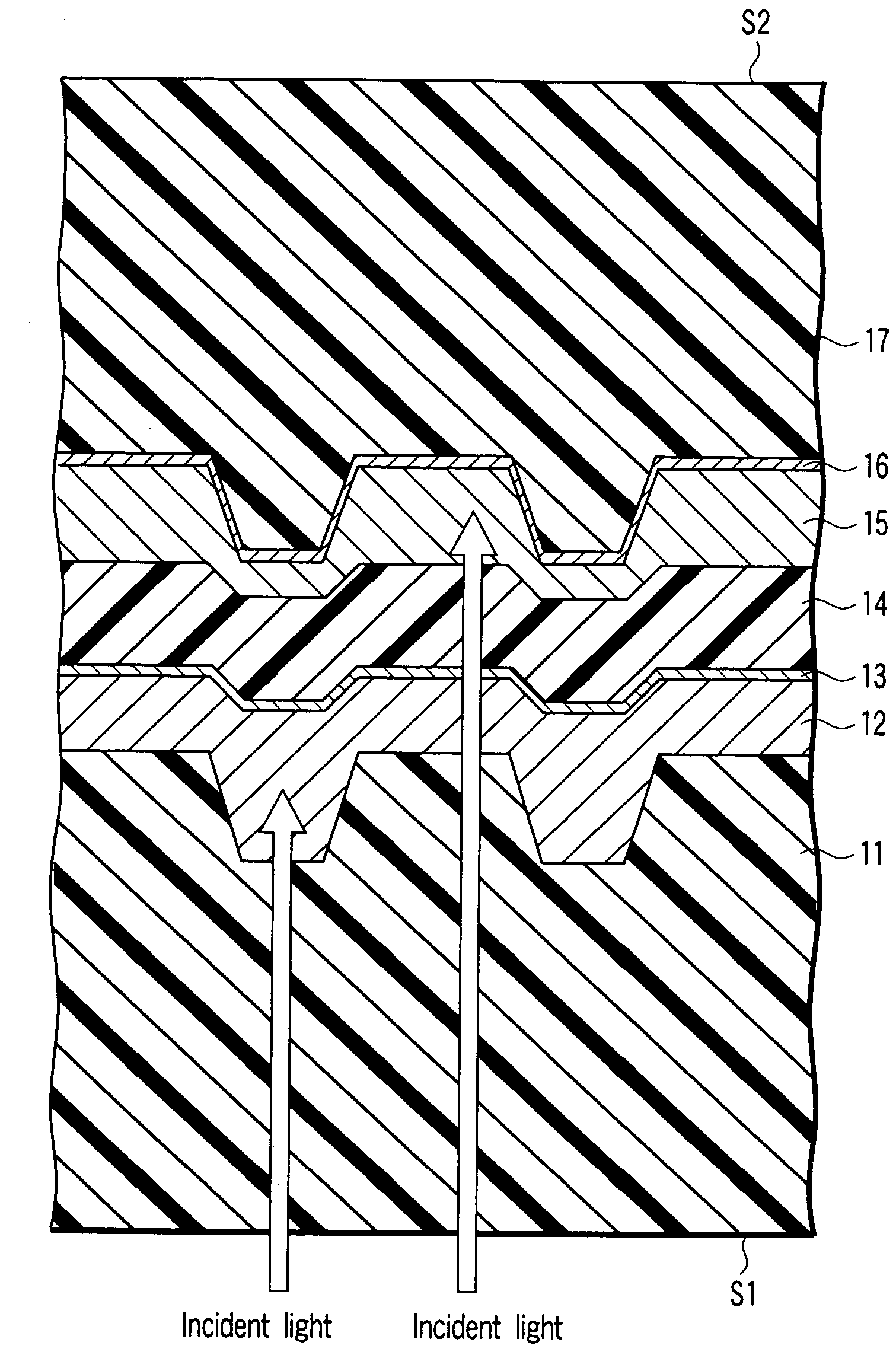
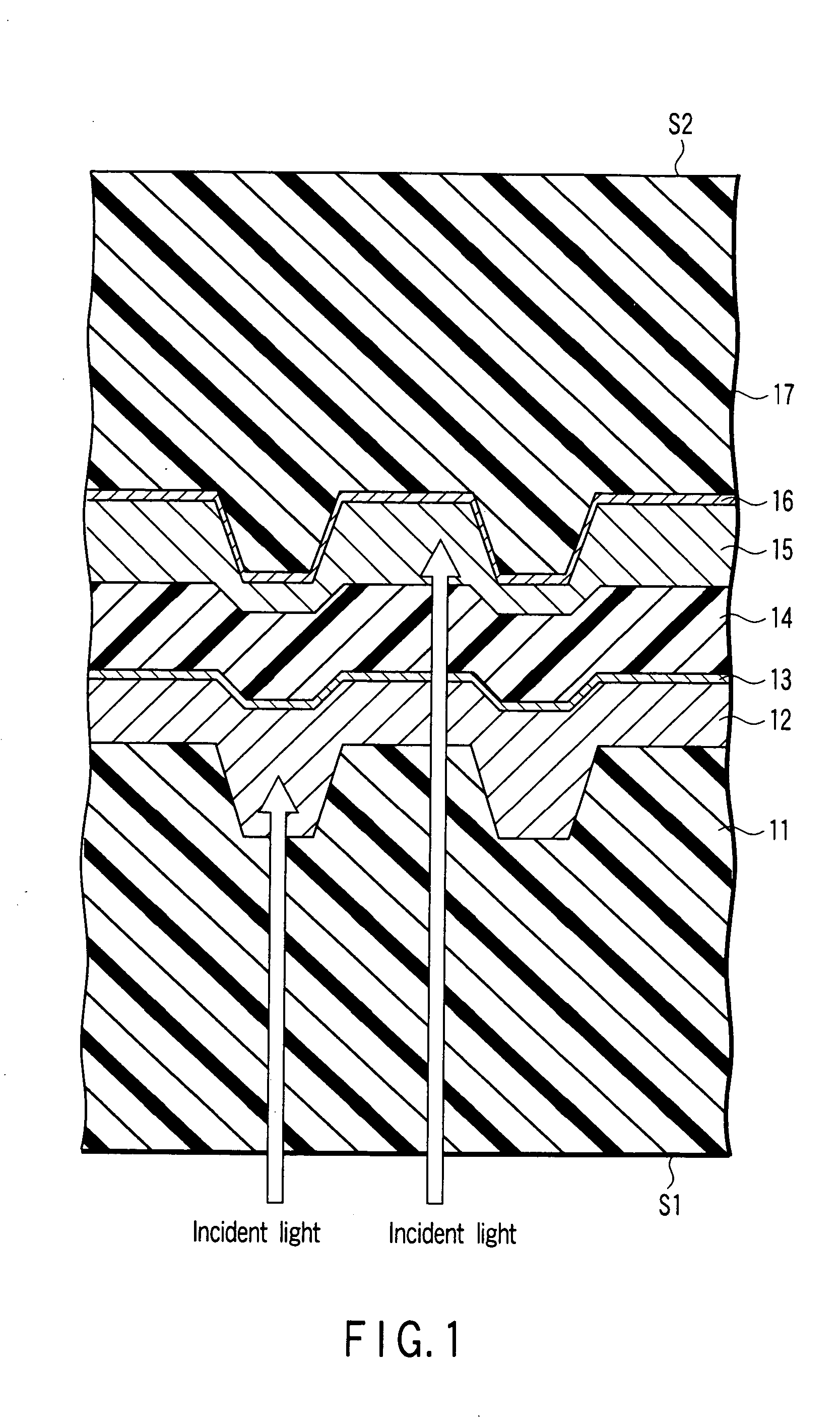
[0026] Hence, in the single-sided / two-layered WORM optical disk according to the present invention, the layer L0 is formed of the H-L recording layer (first recording layer), and the layer L1 is formed of the L-H recording layer (second recording layer). That is, the H-L recording layer (first recording layer) is arranged between the first surface S1 and the L-H recording layer (second recording layer). The H-L recording layer (first recording layer) is used to record the information before the L-H recording layer (second recording layer) is used, and the L-H recording layer (second recording layer) is used after the recording area of the H-L recording layer (first recording layer) is completely used.

[0027] In this arrangement, first, when recording the information on the layer L0, high initial reflectance and stable servo operation can be achieved. In addition to this, since the reflectance of the layer L1 in the unrecorded state is low, the interlayer crosstalk from the layer L1 i...

second embodiment

[0029] Alternatively, in the single-sided / two-layered WORM optical disk according to the present invention, the layer L0 is formed of the L-H recording layer (second recording layer), and the layer L1 is formed of the H-L recording layer (first recording layer). That is, the L-H recording layer (second recording layer) is arranged between the first surface S1 and the H-L recording layer (first recording layer). Also, the H-L recording layer (first recording layer) is used to record the information before the L-H recording layer (second recording layer) is used, and the L-H recording layer (second recording layer) is used after the recording area of the H-L recording layer (first recording layer) is completely used.

[0030] In this arrangement, first, when recording the information on the layer L1, high initial reflectance and stable servo operation can be achieved. In addition to this, since the reflectance of the layer L0 in the unrecorded state is low, the interlayer crosstalk from ...


PUM

PropertyMeasurementUnit
thicknessaaaaaaaaaa
diameteraaaaaaaaaa
diameteraaaaaaaaaa

Abstract

An optical disk according to an example of the present invention includes the first and second recording layers on which pieces of information can be recorded by undergoing a change in properties when irradiated with a laser beam. The first recording layer has the first reflectance characteristic in which the reflectance in an information recorded state is lower than that in an information unrecorded state. The second recording layer has the second reflectance characteristic in which the reflectance in the information recorded state is higher than that in the information unrecorded state.

Description

CROSS-REFERENCE TO RELATED APPLICATIONS [0001] This application is based upon and claims the benefit of priority from prior Japanese Patent Application No. 2004-220742, filed Jul. 28, 2004, the entire contents of which are incorporated herein by reference. BACKGROUND OF THE INVENTION [0002] 1. Field of the Invention [0003] The present invention relates to, e.g., a WORM optical disk. The present invention also relates to an information playback apparatus which plays back information recorded on such a WORM optical disk. [0004] 2. Description of the Related Art [0005] In recent years, various optical disks have been introduced, and the research and development of the various optical disks have been enthusiastically conducted. For example, in Jpn. Pat. Appln. KOKAI Publication No. 2003-051137, the optical disk having a plurality of recording layers is disclosed. In this reference, a technique of equalizing the signal strengths of the layers to obtain stable signal characteristics in an...

Claims


Application Information

Patent Timeline
Patent Type & Authority Applications(United States)
IPC IPC(8): G11B7/24G11B7/24027G11B7/24035G11B7/24038G11B7/24097
CPCG11B7/00736G11B7/24038G11B7/246G11B7/2467G11B7/2472G11B2007/24612G11B7/2534G11B7/256G11B7/2585G11B7/259G11B7/248
Inventor OOTERA, YASUAKI
Owner KK TOSHIBA
Why Eureka
Try Eureka