
Ventilation system with axial fan and integrated accelerator/deflector

Inactive Publication Date: 2006-02-02
LAUZON GHISLAIN
View PDF8 Cites 7 Cited by
  • Summary
  • Abstract
  • Description
  • Claims
  • Application Information

AI Technical Summary

Benefits of technology

[0013] The present invention eliminates the backflow and air leak problems through a positioning of the axial fan which is assembled between two walls of the ventilator housing and using a sealing element between the fan and the housing. This type of assembly, when used in combination with an accelerator / deflector integrated to the housing, improves the fluid flow through the ventilator and therefore results in improved performance with respect to the ventilating capacity of the system. The accelerator / deflector improves the efficiency in terms of flow (inft3 / min) at the outlet of the ventilator, as it decreases turbulence in the flow.
[0015] The system according to the present invention not only results in improved performance with respect to overall air flow, but also results in remarkable acoustic qualities surpassing those of existing ventilation systems under similar conditions. In addition, as opposed to systems that currently exist in the market, the noise level of the ventilator of the present invention does not increase proportionally with an increase in the airflow going through it.

Problems solved by technology

Such a configuration causes turbulence problems in the fluid flow to be evacuated as well as creating phenomena of air backflow and noise.
Another problem associated with standard ventilation systems arises from the transmission of vibrations from the motor to its support structure, with the noise generated by this transmission.
Unfortunately, prior art devices in this field frequently are prone to premature clogging and corrosion, while having disappointing performances in terms of ventilating capacity.
In spite of the teachings of prior art, the above-described problems and issues with standard ventilation systems remain.

Method used


Image

  • Ventilation system with axial fan and integrated accelerator/deflector
  • Ventilation system with axial fan and integrated accelerator/deflector
  • Ventilation system with axial fan and integrated accelerator/deflector

Examples


Embodiment Construction

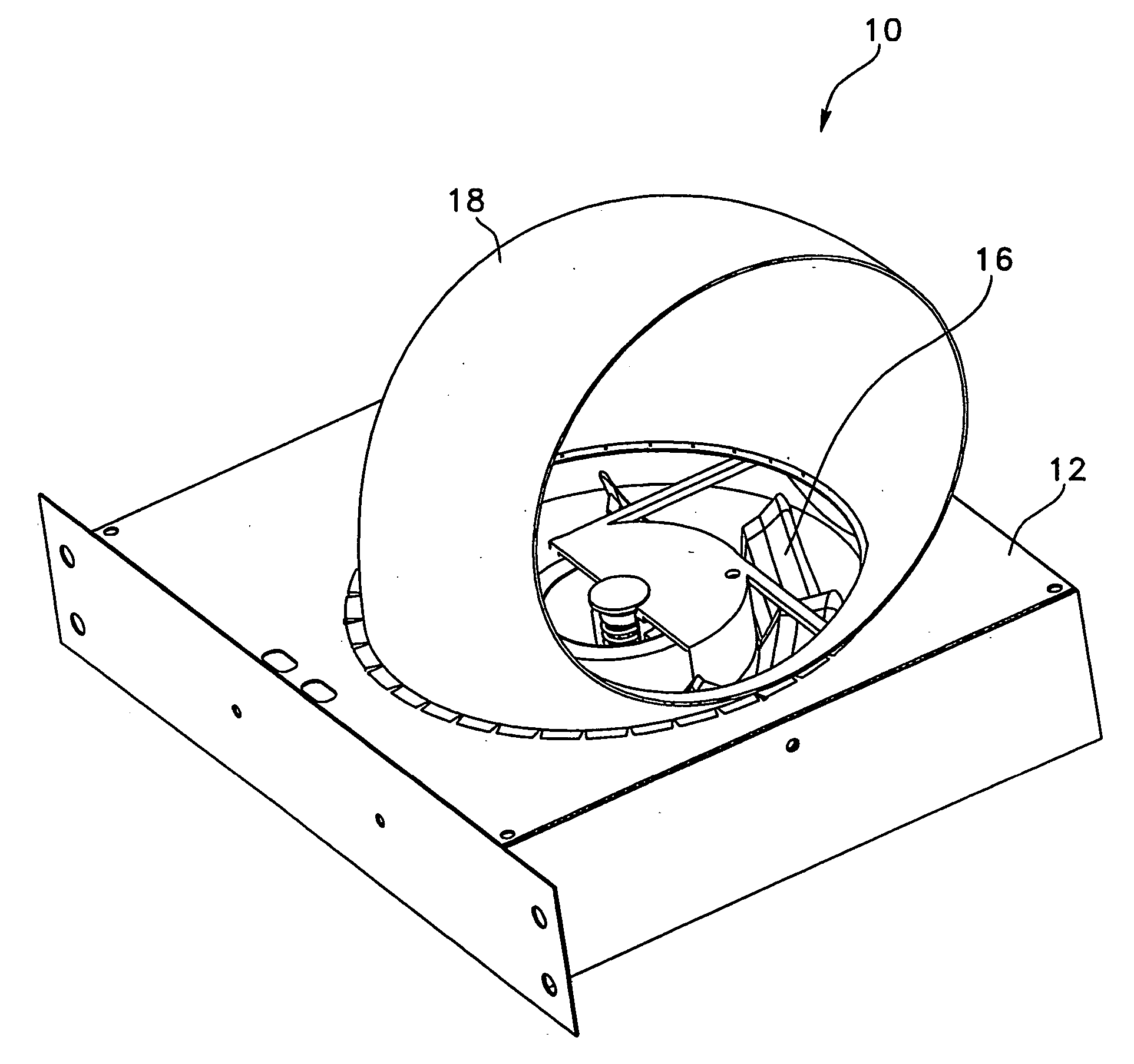
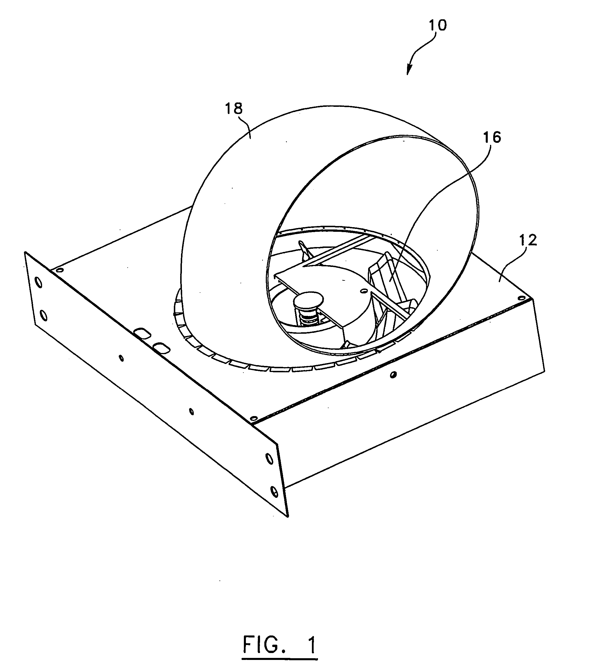
[0024] In the first preferred embodiment of the invention shown in FIGS. 1 and 5, the ventilation system (10) for air or other gaseous fluids comprises a housing (12) through which the air or fluid flows. An axial fan (16) is fixed to the housing (12). The ventilation system (10) also comprises an accelerator / deflector (18) used to improve the air or fluid flow through the housing (12).

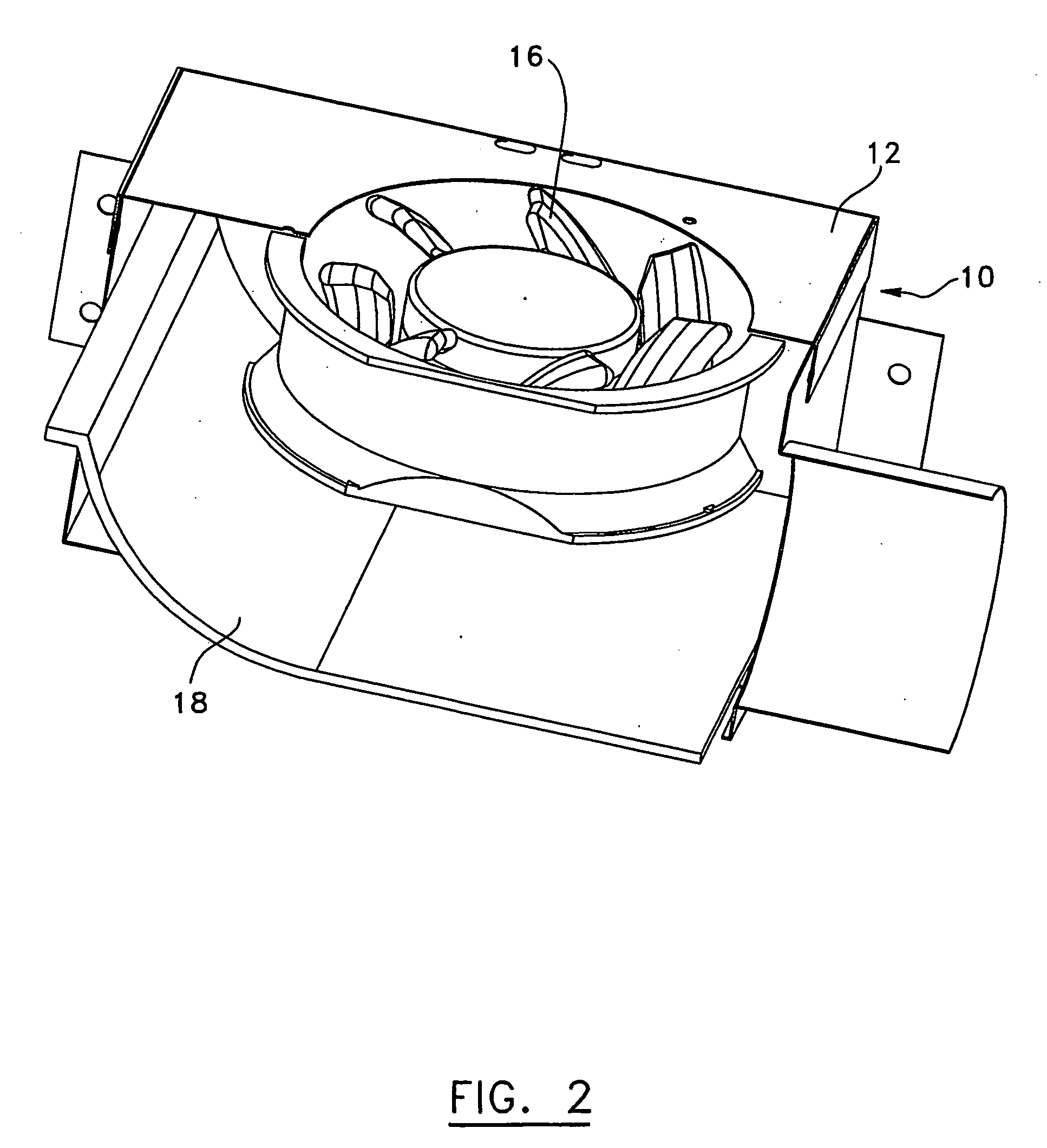
[0025]FIG. 2 shows another type of ventilation system (10) according to a second preferred embodiment of the invention, wherein the accelerator / deflector (18) is mounted within the ventilation system housing (12).

[0026]FIG. 3 shows a cut perspective view of a ventilation system (10) according to a third preferred embodiment of the invention, wherein an accelerator / deflector (18) similar to the one shown in FIG. 1 is mounted within the ventilation system housing (12).

[0027] As shown in FIG. 4, the axial fan (16) comprises a motor (20) in which two sets of ball bearings (24 and 26) are installed on e...


PUM


Abstract

A ventilation system for an air or gaseous fluid has a housing having an inlet (50) and an outlet (52), an axial fan (16) and an accelerating / deflecting structure (18). The axial fan has a casing (36) attached to the housing. Moreover, the axial fan (16) has a motor mounted within the casing and blades (32) also mounted within the casing to generate a flow of said fluid in an axial direction. The accelerating / deflecting structure (18) is devised and positioned to orient the flow generated by the axial fan (16) in a direction transverse to said axial direction. The accelerating / deflecting structure (18) can either be mounted upstream or downstream of the axial fan (16). Furthermore, the accelerating / deflecting structure (18) can either be mounted within or outside the housing.

Description

RELATED APPLICATION(S) [0001] This application is a continuation of International Patent Application No. PCT / CA2004 / 000179 filed on Feb. 10, 2004, which claims benefit of Canadian Patent Application Nos. 2,418,636 and 2,447,334 filed on Feb. 10, 2003 and Oct. 31, 2003 respectively, which are herein incorporated by reference.FIELD OF THE INVENTION [0002] The present invention generally relates to fans used in a residential, commercial, industrial and institutional context. More precisely, the invention relates to a new ventilation system with an axial fan and, preferably, an integrated accelerator / deflector. BACKGROUND OF THE INVENTION [0003] In standard ventilation systems, in particular those used in bathrooms, the fan motor is always fixed to a support, either on an inner ventilator wall opposite the air inlet or on a wall adjacent to the inlet. Such a configuration causes turbulence problems in the fluid flow to be evacuated as well as creating phenomena of air backflow and noise...

Claims


Application Information

Patent Timeline
IPC IPC(8): F04B35/04F04B17/00F04D29/04F04D29/059F04D29/54F24F7/007
CPCF04D29/059F24F7/007F04D29/541
Inventor LAUZON, GHISLAIN
Owner LAUZON GHISLAIN
Learn More