Eureka AIR delivers breakthrough ideas for toughest innovation challenges, trusted by R&D personnel around the world.

High-lift multi-stage side channel pump with gas-liquid mixed flow

A high-lift, side channel technology, applied to radial flow pumps, parts of pumping devices for elastic fluids, pumps, etc., can solve the problems affecting reliability and safety, side channel pumps cannot operate, Poor cavitation ability and other problems, to avoid energy loss, improve hydraulic performance and anti-cavitation ability, eliminate backflow or deflow effect

Inactive Publication Date: 2018-12-28
JIANGSU UNIV
View PDF6 Cites 3 Cited by
  • Summary
  • Abstract
  • Description
  • Claims
  • Application Information

AI Technical Summary

Problems solved by technology

Since the side channel pump is also a type of vortex pump, its anti-cavitation ability is poor. The performance of the runner pump will change greatly due to cavitation. According to the amount of gas content, the side runner pump will have corresponding vibration and noise. In severe cases, the side runner pump will not be able to operate, which will affect the reliability and safety of the system. , so how to improve the cavitation resistance and hydraulic performance of the multistage side channel pump by optimizing the flow parts, and then improve its gas-liquid mixed transportation capacity, is an urgent problem to be solved in the design and development of the multistage side channel pump.
[0003] After searching, no documents and patents identical to the high-lift multi-stage side channel pump proposed by the present invention that can realize gas-liquid mixed transportation have been found.

Method used


Image

  • High-lift multi-stage side channel pump with gas-liquid mixed flow
  • High-lift multi-stage side channel pump with gas-liquid mixed flow
  • High-lift multi-stage side channel pump with gas-liquid mixed flow

Examples


Embodiment Construction

[0021] The present invention will be further described below in conjunction with the accompanying drawings and specific embodiments.

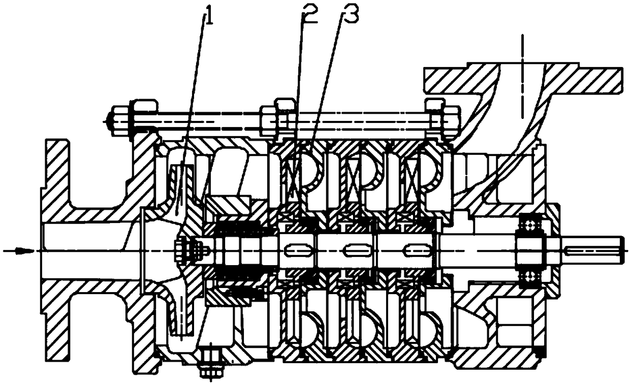
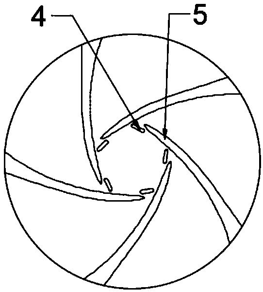
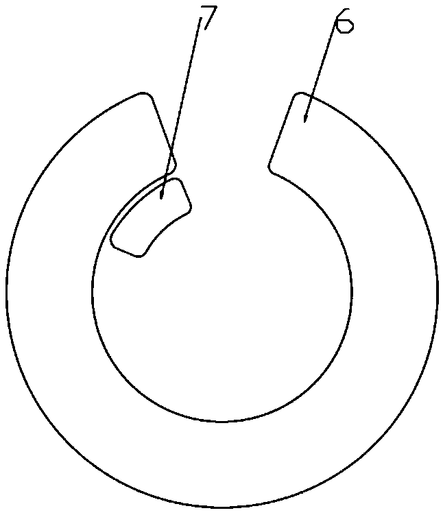
[0022] combined with figure 1 The schematic diagram of the structure of the multi-stage side channel pump is shown. The main components of the multi-stage side channel pump are the first stage impeller 1, the radial star impeller 2, and the arc flow channel 3; the fluid enters from the first stage impeller 1, and the gap drainage impeller shows Such as figure 2 As shown, when the fluid flows into the first-stage impeller 1, because there is a gap between the leading vane 4 and the trailing vane 5, part of the fluid will flow from the pressure side of the blade to the suction side through the gap, and because the deflection of the leading vane 4 If the position is set, the area of ​​the inlet area of ​​the flow channel will increase, making the distribution of the velocity field inside the flow channel more uniform, which will also eliminate t...


PUM


Abstract

The invention discloses a high-lift multi-stage side channel pump with gas-liquid mixed flow, and relates to the technical field of multi-stage side channel pump design. The high-lift multi-stage sidechannel pump includes first-stage impellers, radial starlike impellers and arc-shaped flow channels. The first-stage impellers are centrifugal impellers for improving the anti-cavitation capability,gaps are adapted to drainage a blade, the gaps are located near inlets, the flow conditions at fluid inlets can be improved, the operating efficiency of the side channel pump is improved, and the anti-cavitation capability of the multi-stage side channel pump is further improved. The radial starlike open-type impellers are used for impellers of the second-stage and remaining stages, and the arc-shaped closed channels are added on the right sides of the open-type impellers; the open-type impellers and the closed channels are combined to further improve the anti-cavitation capability of the multi-stage side channel pump, the self-absorption ability can be further improved. The finally-assembled side channel pump can be stably operated in a conveying medium with a high gas content to meet theoperating condition requirements of gas-liquid mixed flow.

Description

technical field [0001] The invention relates to the technical field of multi-stage side channel pump design, in particular to a high-lift multi-stage side channel pump capable of gas-liquid mixed transport. Background technique [0002] The structure of the present invention is based on a multi-stage side channel pump. The side channel pump belongs to the ultra-low specific speed vane pump type. It is named because there is a space channel on one side of the impeller. The inter-radial vane pump is a new type of vortex pump with a small operating flow but a relatively high lift. Since the side channel pump is also a type of vortex pump, its anti-cavitation ability is poor. The performance of the runner pump will change greatly due to cavitation. According to the amount of gas content, the side runner pump will have corresponding vibration and noise. In severe cases, the side runner pump will not be able to operate, which will affect the reliability and safety of the system. ...

Claims


Application Information

Patent Timeline
Patent Type & Authority Applications(China)
IPC IPC(8): F04D1/06F04D29/66F04D29/22F04D29/24
Inventor 张帆陈轲张金凤袁寿其魏雪园
Owner JIANGSU UNIV
Why Eureka
Eureka Blog
Learn More