

High-pressure lever ball float type steam trap
A steam trap and floating ball technology, which is applied in steam traps, mechanical equipment, etc., can solve the problems of unrestricted increase of the wall thickness of the floating ball, the limitation of the maximum working pressure, and the reduction of the service life of the valve, so as to achieve superior sealing performance , long service life, good sealing performance
- Summary
- Abstract
- Description
- Claims
- Application Information
AI Technical Summary
Problems solved by technology
Method used
Image

Examples
Embodiment Construction
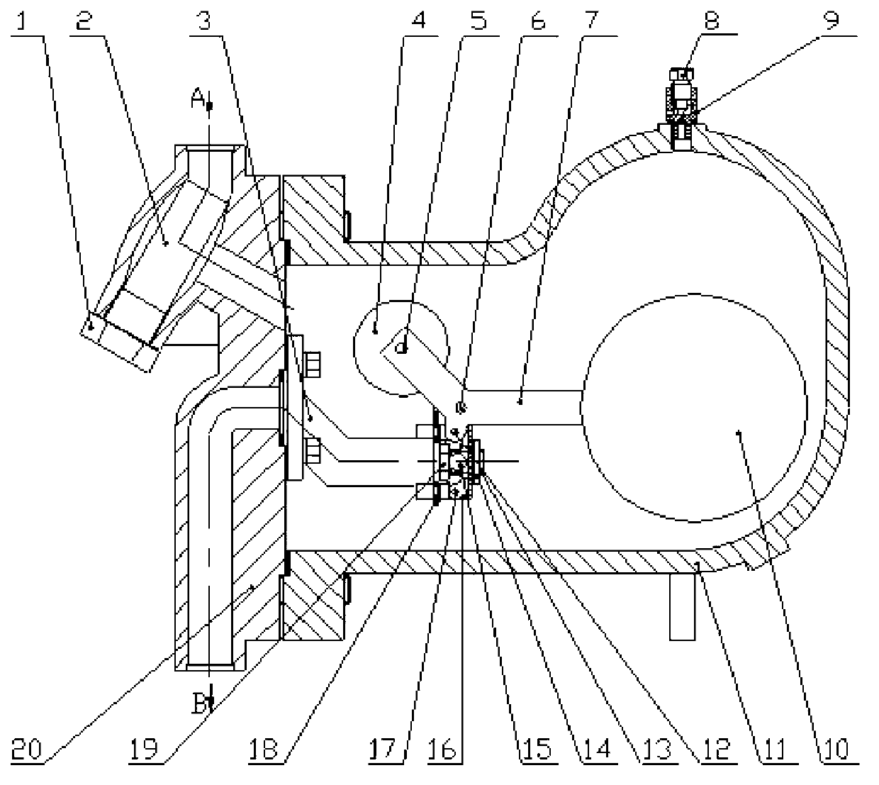
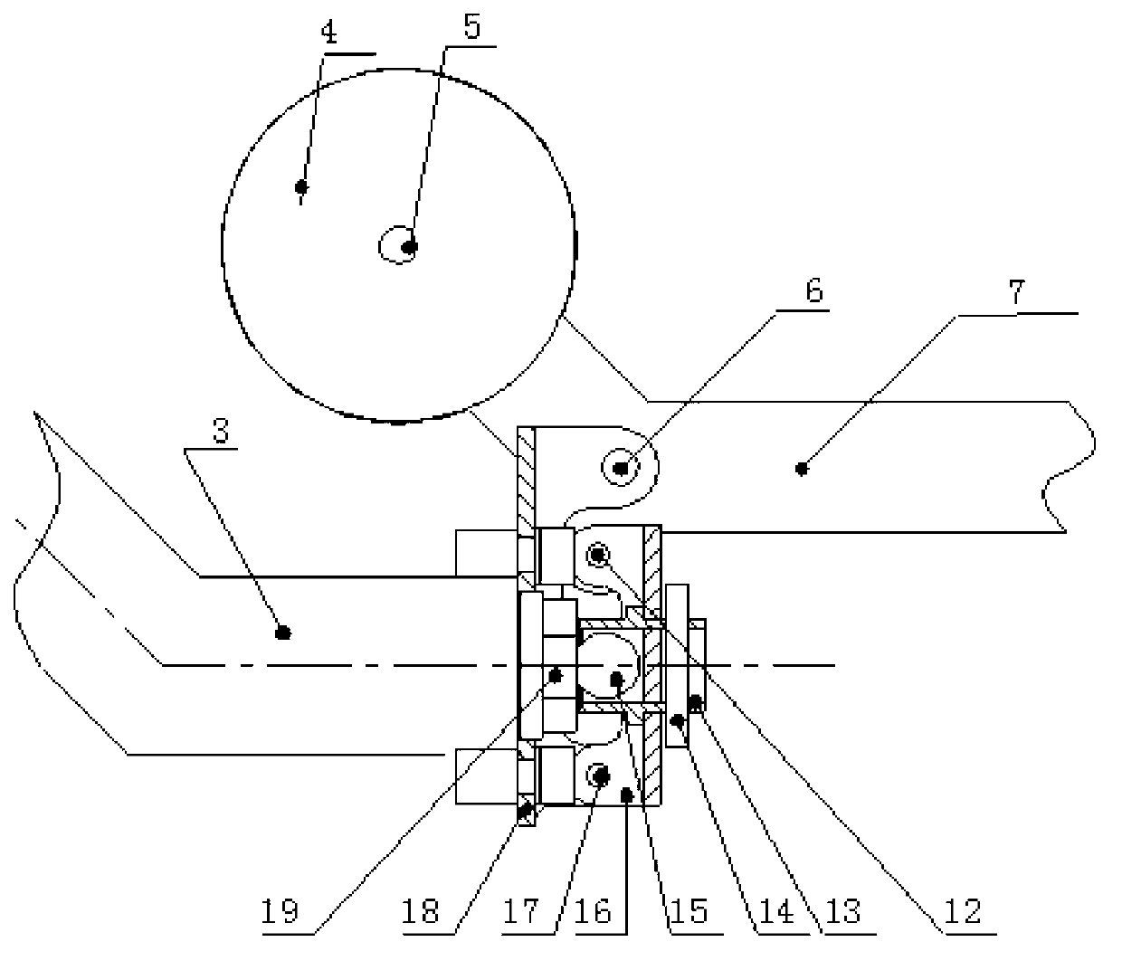
[0023] exist figure 1 In the described high-pressure lever float type steam trap, the steam trap has a valve body 11 and a valve cover 20 forming a sealed pressure vessel with the valve body, and the valve body 11 and the valve cover 20 are fixedly connected by bolts to form the valve body of the present invention. shell. The threaded hole at the high point of the cavity of the valve body 11 is fixedly connected with the needle valve seat 9, and the non-condensable gas inside the present invention is discharged by rotating the needle valve disc 8 connected with the needle valve seat 9. A drum-shaped inner hole channel is designed at the medium inlet end of the valve cover 20, and a filter screen 2 is installed on the inner hole channel. A filter screen 2 fixed on the valve cover 20 by a screw plug 1 is provided at the medium inlet A, and impurities in the filter screen 2 can be discharged by unscrewing the screw plug 1 . The inner end surface of the valve cover 20 is provide...
PUM
 Abstract
Description
Claims
Application Information