Apparatus for the percutaneous marking of a lesion

a technology of percutaneous positioning and radiopaque markers, applied in the field of intravenous markers, can solve the problems of reducing the size of the biopsy, inaccurate identification of the biopsy location, and error in determining the biopsy location, so as to facilitate subsequent determination and effectively fill the marker recess

Active Publication Date: 2006-02-02
BARD PERIPHERAL VASCULAR +1
View PDF104 Cites 66 Cited by
  • Summary
  • Abstract
  • Description
  • Claims
  • Application Information

AI Technical Summary

Benefits of technology

[0008] The present invention provides a biopsy marking apparatus for the percutaneous placement of a marker at a biopsy site in a tissue mass to facilitate subsequent determination of the location of the biopsy site. The biopsy marking apparatus comprises an introducer having a handle to be grasped by a user, a cannula, a stylet, and a radiopaque marker. The cannula has a proximal end mounted to the handle and a distal end defining an insertion tip. The stylet is slidably received within the cannula for movement between a ready position in which a distal end of the stylet is spaced inwardly from the cannula tip to form a marker recess between the distal end of the stylet and the cannula tip, and an extended position in which the distal end of the stylet extends at least to the cannula tip to effectively fill the marker recess.
[0013] In another aspect, the invention also provides a radiopaque marker having a marker body and an anchor extending away from the body for fixing the location of the radiopaque marker in a tissue mass by the tissue mass prolapsing about the anchor. Preferably, the body has an interior hollow portion forming an air trap to enhance the ultrasound characteristic of the radiopaque marker.

Problems solved by technology

One problem commonly encountered, especially in breast biopsies, is that the lesion is so small that the biopsy reduces its size to the extent that it is no longer visible by the imaging method employed.
A significant disadvantage is that the marker is not always completely ejected from the cannula or can be drawn back into or toward the cannula by the vacuum created upon the withdrawal of the cannula, which results in the marker being moved from the intended site, leading to inaccurate identification of the location of the biopsy area.
A second major disadvantage is that current markers have a tendency to migrate within the tissue, also causing error in determining the biopsy location.

Method used


Image

  • Apparatus for the percutaneous marking of a lesion
  • Apparatus for the percutaneous marking of a lesion
  • Apparatus for the percutaneous marking of a lesion

Examples


Embodiment Construction

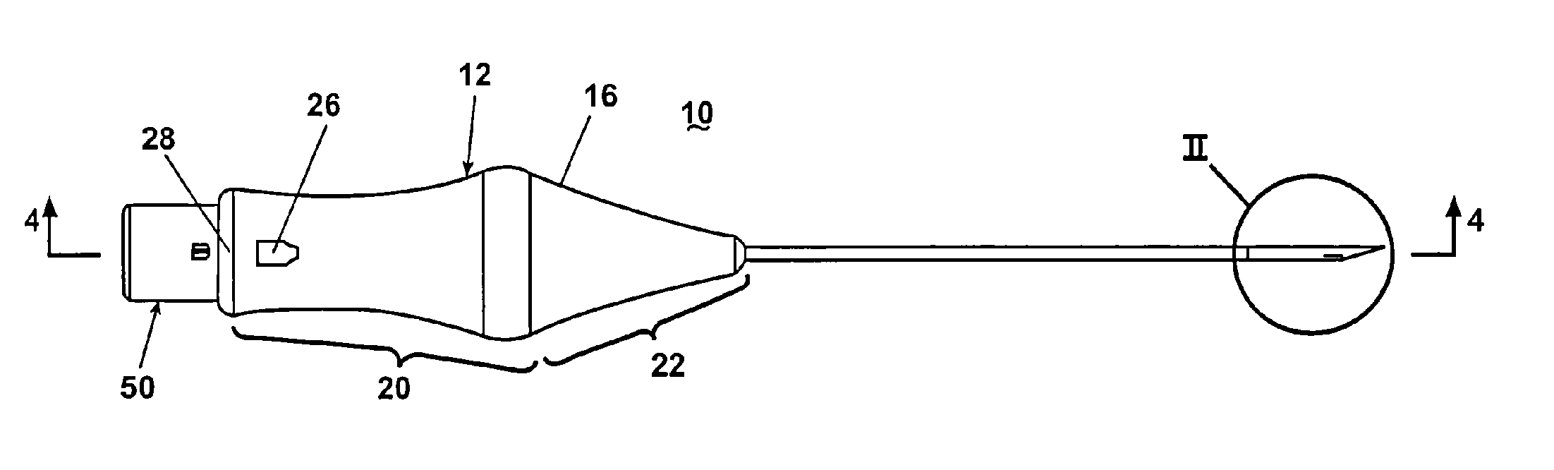
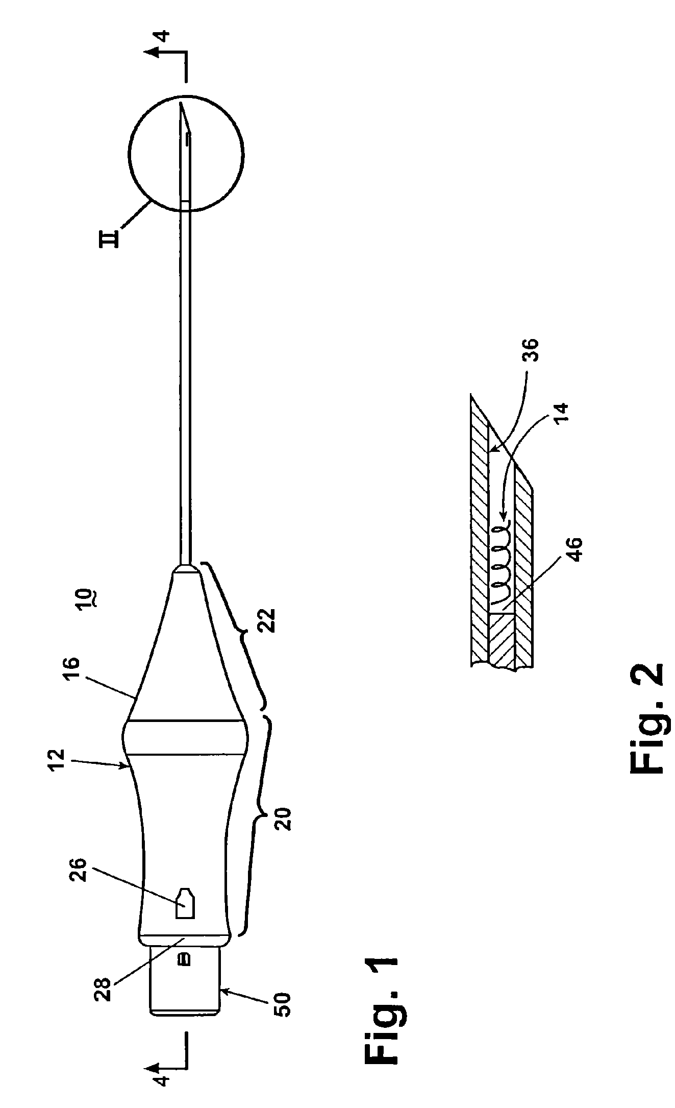
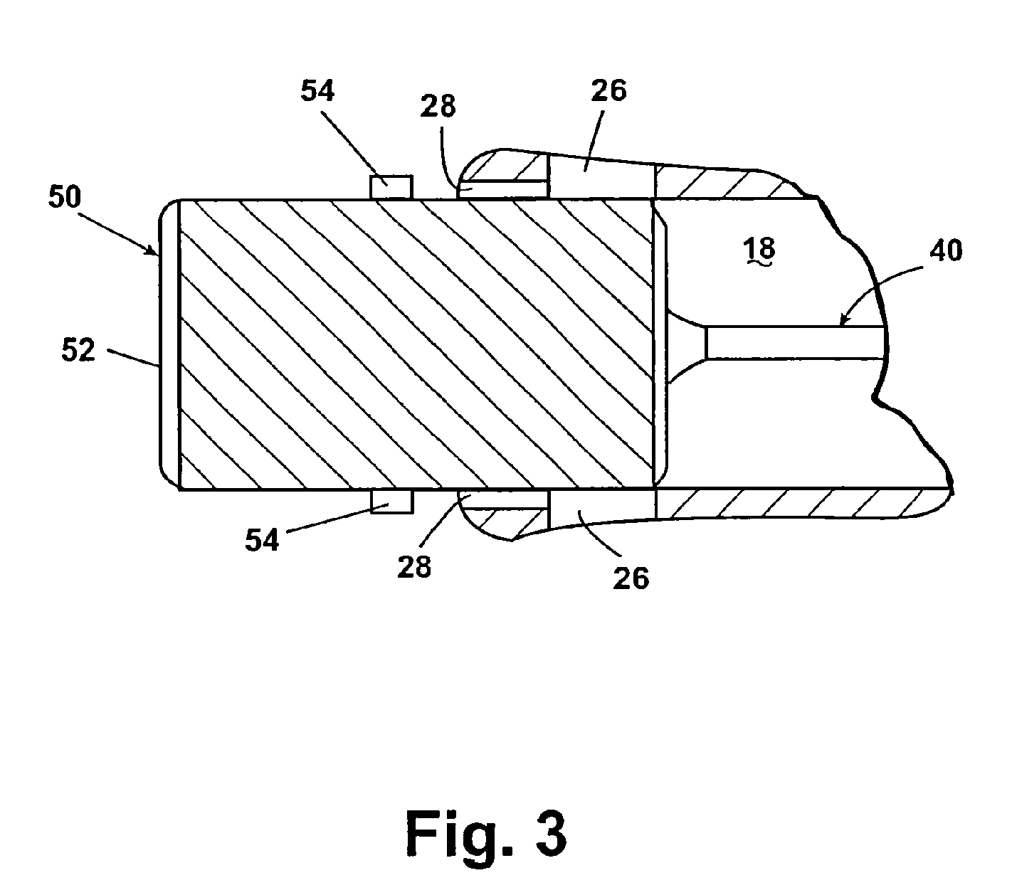
[0031] FIGS. 1 to 4 illustrate a biopsy marking apparatus 10 according to the invention, which is capable of the percutaneous placement of a radiopaque marker at the location of a tissue biopsy. The biopsy marking apparatus 10 comprises an introducer 12 and a radiopaque marker 14 (FIG. 2) contained within the introducer 12. The introducer 12 includes a handle 16 having a hollow interior 18. The handle 16 comprises a grip portion 20 from which extends a tapered nose portion 22. The grip portion 20 defines a rear opening 24 that provides access to the hollow interior 18. A pair of detents 26 are formed in the grip portion 20 near the rear opening 24. Channels 28 are formed on the interior surface of the grip portion 20 and extend from the rear opening 24 to the detents 26.

[0032] The nose portion 22 comprises a guide passage 30 extending from the tip of the nose portion 22 to the hollow interior 18 of the handle 16. The guide passage 30 decreases in diameter inwardly from the tip of t...


PUM


Abstract

A biopsy marking apparatus for placing a radiopaque marker at the location of a percutaneous biopsy. The biopsy marking apparatus comprises an introducer in combination with a radiopaque marker. The introducer ejects the radiopaque marker at the location of the biopsy. The introducer is configured to completely eject the radiopaque marker and prevent it from being subsequently drawn into the introducer as the introducer is removed from the biopsied tissue mass. The radiopaque marker has enhanced radiopaque characteristics and enhanced non-migration characteristics.

Description

CROSS-REFERENCE TO RELATED APPLICATION [0001] This application is a divisional of U.S. patent application Ser. No. 10 / 421,517 filed Apr. 23, 2003, which is a divisional of U.S. patent application Ser. No. 09 / 596,610, filed Jun. 16, 2000, which claims the priority of U.S. provisional patent application Ser. No. 60 / 139,580, filed Jun. 17, 1999. All of the aforementioned application are incorporated herein by reference.FIELD OF THE INVENTION [0002] This invention relates generally to an apparatus for the percutaneous positioning of a radiopaque marker for identifying the location of a lesion in a stereotactic biopsy procedure. More particularly, the invention relates to an introducer having a hollow cannula in combination with a movable stylet and a radiopaque marker disposed within the cannula and ejected from it by movement of the stylet. DESCRIPTION OF THE RELATED ART [0003] Tissue biopsies are commonly performed on many areas and organs of the body where it is desirable to ascertai...

Claims


Application Information

Patent Timeline
Patent Type & Authority Applications(United States)
IPC IPC(8): A61B17/34A61B10/00A61B19/00
CPCA61B17/3468A61B19/54A61M5/007A61B2019/5487A61B8/481A61B2019/5408A61B90/39A61B2090/3908A61B2090/3987A61B2090/3925A61B2090/3966A61B2090/3995
Inventor CHESBROUGH, RICHARD M.FIELD, STEVEN E.GOOSEN, RYAN L.ZERFAS, JEFFDAVIS, RICHARD E.
Owner BARD PERIPHERAL VASCULAR
Why Eureka
Try Eureka