
Branch predicting apparatus and branch predicting method

a branch prediction and branch prediction technology, applied in the field of branch prediction apparatus and branch prediction method, can solve the problems of inability to fix the return target of the return instruction, the prediction is not always correct, and the return instruction is less effectiv

Inactive Publication Date: 2006-02-02
FUJITSU LTD
View PDF13 Cites 14 Cited by
  • Summary
  • Abstract
  • Description
  • Claims
  • Application Information

AI Technical Summary

Benefits of technology

[0011] It is an object of the present invention to solv...

Problems solved by technology

The branch prediction has, however, a major disadvantage that, when the prediction is missed, it is necessary to flash the pipeline and re-starts the processing at the branch instruction.
However, it is less effective for a return instruction from a sub-routine.
Normally, however, the sub-routine is called from every location of the program, so that a return target of the return instruction is not fixed.
As a result, even when the branch target is predicted according to the history, the prediction is not always correct.
However, as already explained, the accuracy for the prediction based on the branch history is not high for the return instruction.
Thus, the technique disclosed in the above literature has the problem that the branch prediction accuracy is deteriorated depending on a return-instruction detection timing.

Method used


Image

  • Branch predicting apparatus and branch predicting method
  • Branch predicting apparatus and branch predicting method
  • Branch predicting apparatus and branch predicting method

Examples


first embodiment

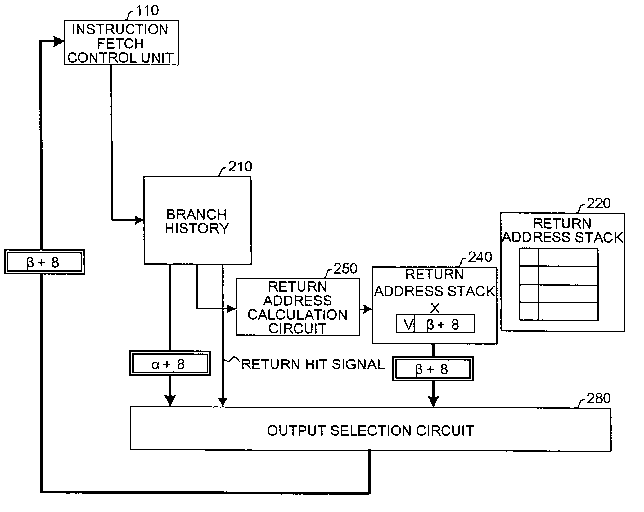
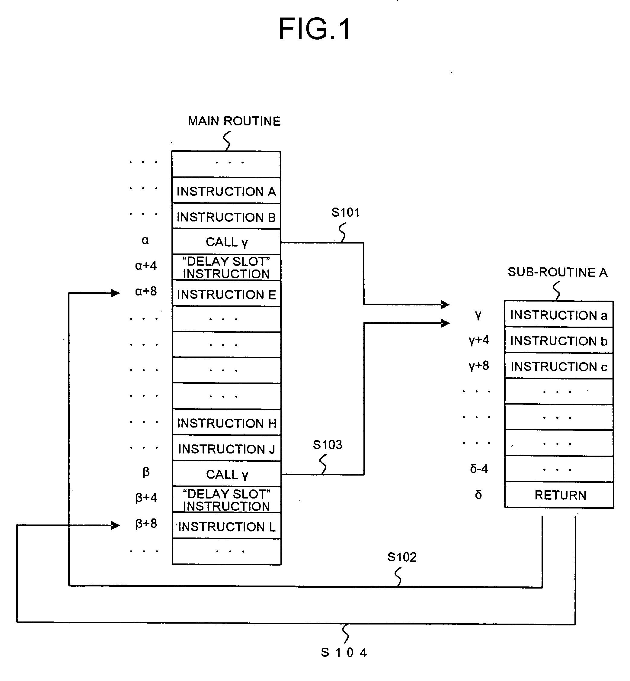
[0039]FIG. 1 is an explanatory view for a program used to explain a principle of a branch predicting method according to the present invention.

[0040] As shown in FIG. 1, this program executes a call instruction for calling a sub-routine A, at an address α (at a step S101). The sub-routine A ends in response to a return instruction at an address δ, and the program returns to an address α+8 in a main routine to continue a processing (at a step S102).

[0041] The reason that the return address is α+8 is that an instruction length of a processor that executes this program is four bytes and that an instruction in the delay slot always follows a branch instruction. When a type of the processor differs from that used in the present embodiment, an increment of the address often differs from +8.

[0042] The program executes a call instruction for calling again the sub-routine A, at an address β (at a step S103). The sub-routine A ends in response to the return instruction at the address δ, and...

second embodiment

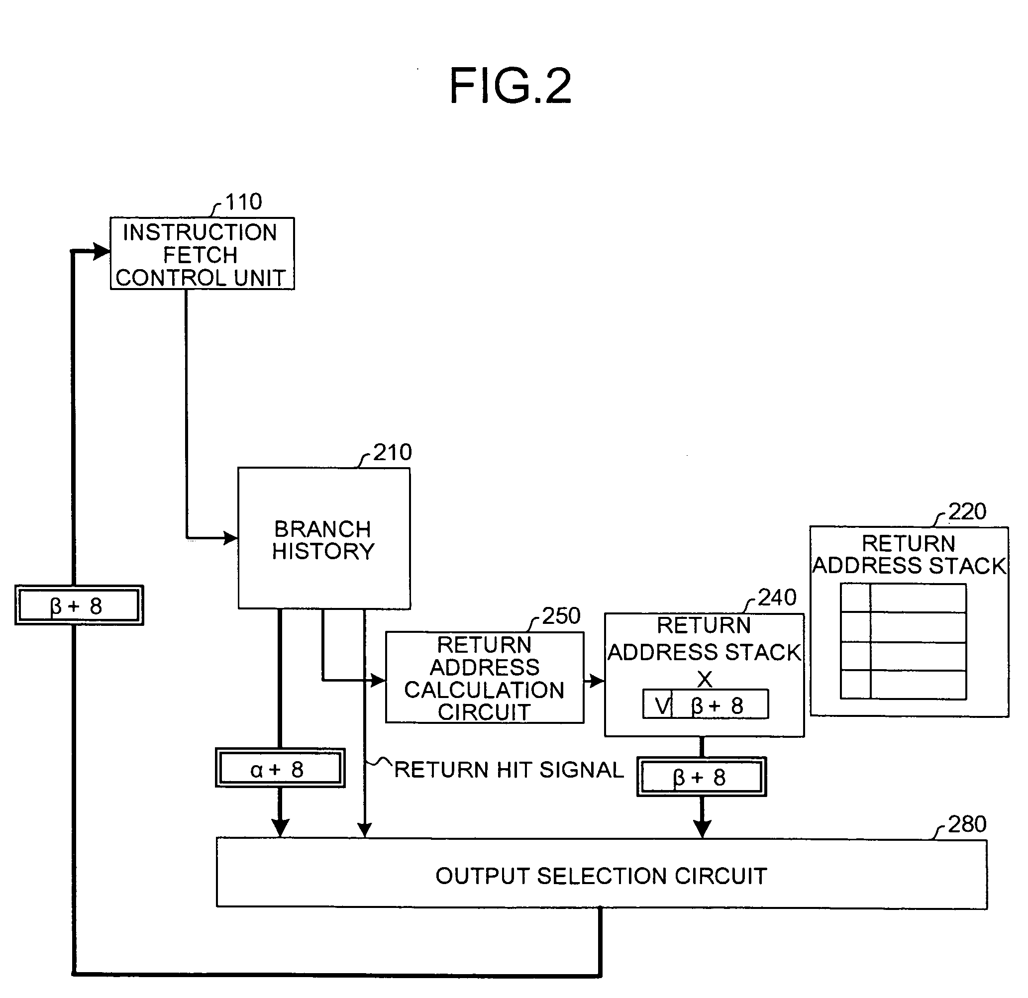
[0106]FIG. 14 is a block diagram of the configuration of the branch predicting apparatus according to the present invention.

[0107] Since the apparatuses exterior of a branch predicting apparatus 300 are equal to those according to the first embodiment, only the interior of the branch predicting apparatus 300 will be explained. As shown in FIG. 14, the branch predicting apparatus 300 includes a branch history 310, a return address stack X320, a valid control circuit 330, a return address calculation circuit 340, and an output selection circuit 350.

[0108] The branch history 310 is an apparatus that stores a pair of the address of the branch instruction executed by the branch reservation station 150 and the branch target in response to the instruction together with the other information flag. The call instruction and the return instruction are also a kind of branch instruction, so that a branch result of the instruction is stored in the branch history 310.

[0109] When acquiring the ad...


PUM


Abstract

A return address in response to a return instruction corresponding to a call instruction is stored in a return address stack when a branch history detects presence of the call instruction. When the branch history detects the presence of the return instruction before a branch reservation station completes executing the call instruction, the return address in response to the return instruction is not stored in the return address stack. If so, an output selection circuit predicts a correct return target using information stored in the return address stack.

Description

BACKGROUND OF THE INVENTION [0001] 1) Field of the Invention [0002] The present invention relates to a branch predicting apparatus and a branch predicting method for predicting a branch in a pipeline processor, and more particularly, to a branch predicting apparatus and a branch predicting method capable of improving accuracy for predicting a branch target of a return instruction. [0003] 2) Description of the Related Art [0004] Conventionally, a branch predicting method is widely used to accelerate a processing for a pipeline processor. When a branch is present in a program, it is originally necessary to stop a pipeline until the branch is confirmed. The processor that performs a branch prediction, however, predicts the branch and speculatively executes an instruction after the branch prediction. [0005] The branch prediction carries a major advantage that a processing time until the branch is confirmed can be shortened. The branch prediction has, however, a major disadvantage that, ...

Claims


Application Information

Patent Timeline
IPC IPC(8): G06F9/44
CPCG06F9/30054G06F9/3806
Inventor YOKOI, MEGUMIUKAI, MASAKI
Owner FUJITSU LTD
Learn More