
Technique for reduced-tag dynamic scheduling and reduced-tag prediction

a dynamic scheduling and dynamic scheduling technology, applied in the field of dynamic scheduling techniques, can solve the problems of increasing parallelism at the expense of slower scheduler clock speed, increasing design difficulty, and increasing energy consumption of embedded processors

Active Publication Date: 2008-07-08
RGT UNIV OF MICHIGAN
View PDF14 Cites 5 Cited by
  • Summary
  • Abstract
  • Description
  • Claims
  • Application Information

AI Technical Summary

Benefits of technology

The present invention provides a dynamic scheduling scheme that uses reservation stations and a comparator to determine when an operand becomes ready for execution. This allows for efficient execution of instructions and reduces delays in the processing of data. Additionally, the invention predicts the last received operand and schedules execution based on the prediction, further improving efficiency.

Problems solved by technology

While more ILP can be extracted with larger instruction windows (and accordingly larger CAM structures), such an increase in parallelism comes at the expense of slower scheduler clock speed.
Increasing clock speeds and diminishing voltage margins have combined to produce designs that are increasingly difficult to cool.
Additionally, embedded processors are more sensitive to energy usage as these designs are often powered by batteries.

Method used


Image

  • Technique for reduced-tag dynamic scheduling and reduced-tag prediction
  • Technique for reduced-tag dynamic scheduling and reduced-tag prediction
  • Technique for reduced-tag dynamic scheduling and reduced-tag prediction

Examples


Embodiment Construction

[0017]It is to be understood that the present invention may be embodied in other specific forms without departing from its essential characteristics. The illustrated and described embodiments are to be considered in all respects only as illustrative and not restrictive. The scope of the invention is, therefore, indicated by the appended claims rather than by the foregoing description. All changes that come within the meaning and range of equivalency of the claims are to be embraced within their scope.

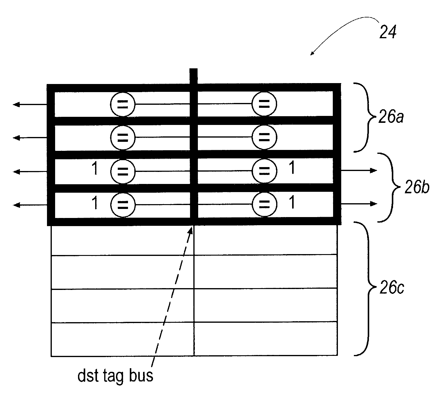
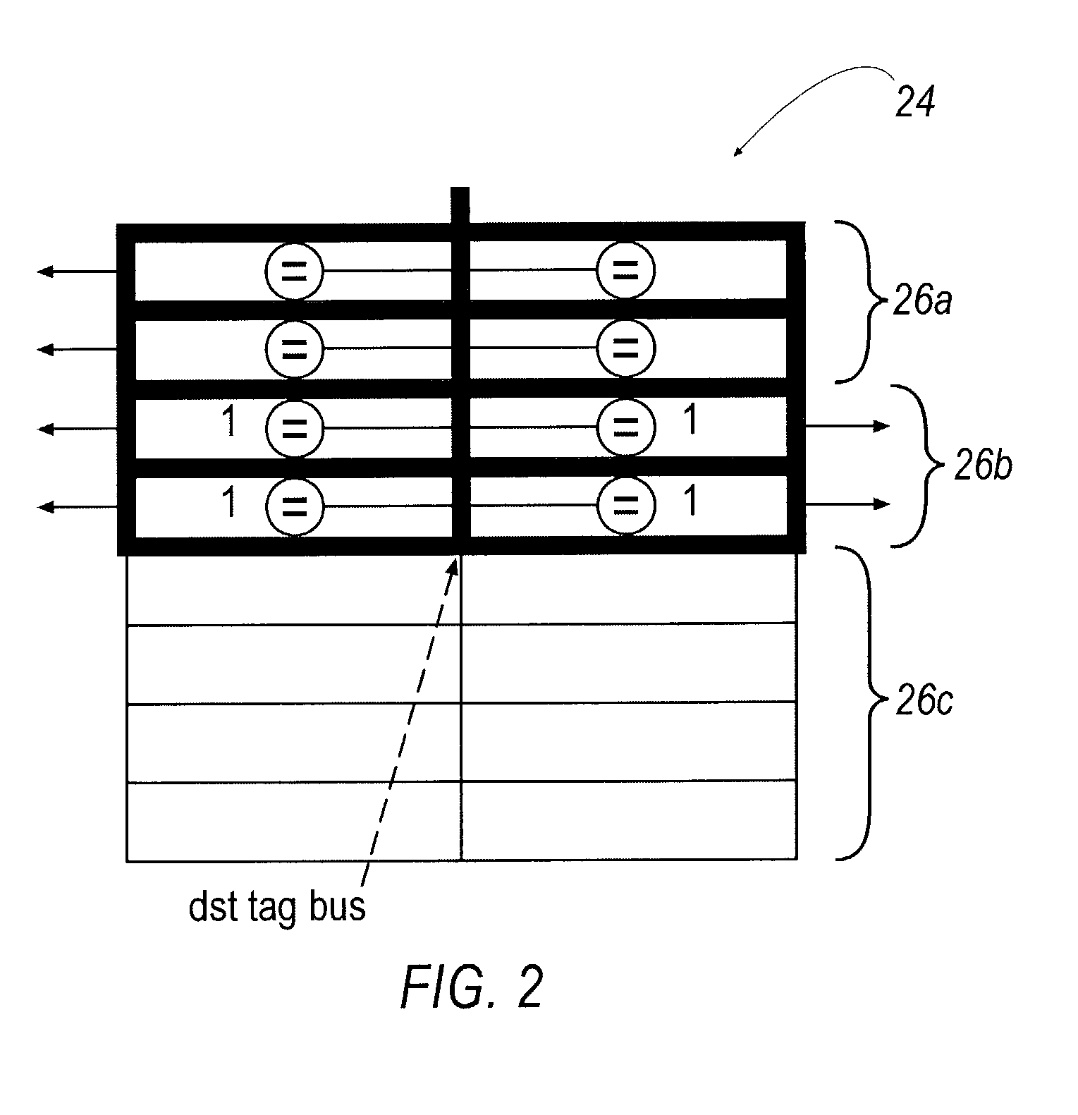
[0018]The present invention is based on most tag scheduler comparisons being superfluous to correct operation of the instruction scheduler. Specifically, most instructions placed into the instruction window do not require two source tag comparators due to one or more operands being ready, or because the operation doesn't require two register operands.

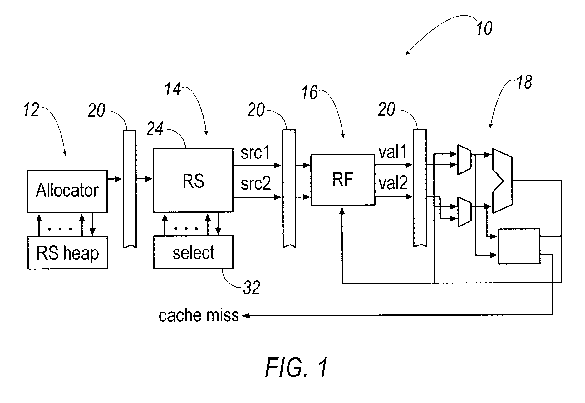
[0019]Referring now to FIG. 1, a dynamic scheduler pipeline 10 according to an aspect of the present invention is shown and described. The...


PUM


Abstract

The present invention provides a dynamic scheduling scheme that uses reservation stations having at least one station that stores an at least two operand instruction. An allocator portion determines that the instruction, entering the pipeline, has one ready operand and one not-ready operand, and accordingly places it in a station having only one comparator. The one comparator then compares the not-ready operand with tags broadcasted on a result tag bus to determine when the not-ready operand becomes ready. Once ready, execution is requested to the corresponding functional unit.

Description

CROSS-REFERENCE TO RELATED APPLICATIONS[0001]This application claims priority based on U.S. Provisional Patent Application No. 60 / 370,027 filed Apr. 4, 2002, the entirety of which is incorporated herein by reference.[0002]This invention was made with government support under Grant #F002303-039305 from the National Science Foundation and Grant #98-DT-660 from MARCO. The government has certain rights in the invention.FIELD OF THE INVENTION[0003]The present invention generally relates to a dynamic scheduling technique, and more particularly, the present invention relates to a dynamic scheduling technique that uses tag elimination to improve the performance of dynamic scheduling.BACKGROUND OF THE INVENTION[0004]In an effort to secure higher levels of system performance, microprocessor designs often employ dynamic scheduling as a technique to extract information level parallelism (ILP) from serial instruction streams. Conventional dynamic scheduler designs house a window of candidate ins...

Claims


Application Information

Patent Timeline
Patent Type & Authority Patents(United States)
IPC IPC(8): G06F15/00G06F9/00G06F9/30G06F9/38
CPCG06F9/3836G06F9/3875G06F9/3844G06F9/3824
Inventor ERNST, DANIEL J.AUSTIN, TODD M.
Owner RGT UNIV OF MICHIGAN
Learn More