Apparatus and methods for removing wedges of a stator core of an electrical machine

a technology of stator core and electrical machine, which is applied in the direction of applying/manufacturing slot closures, windings, and manufacturing tools, etc., can solve the problems of generating a potential for injury to the operator, slipping and tool and core damage, and the wedge halves moving toward

Inactive Publication Date: 2006-02-09
GENERAL ELECTRIC CO
View PDF8 Cites 15 Cited by
  • Summary
  • Abstract
  • Description
  • Claims
  • Application Information

AI Technical Summary

Benefits of technology

[0005] In a further preferred embodiment according to the present invention, there is provided a method for removing wedges in axially extending slots of a stator core of an electrical machine, comprising the steps of (a) disposing a frame within the core extending between diametrically opposite wall portions of the stator core, (b) providing a carriage carrying a cutter head, the carriage being carried by the frame for pivotal m

Problems solved by technology

When biasing the wedges using ripple springs, however, the ripple springs cause the wedge halves to move toward one another as the cut is being made.
That is, the action of the ripple spring causes the wedges to bind the cutting blade, causing sl

Method used


Image

  • Apparatus and methods for removing wedges of a stator core of an electrical machine
  • Apparatus and methods for removing wedges of a stator core of an electrical machine
  • Apparatus and methods for removing wedges of a stator core of an electrical machine

Examples


Embodiment Construction

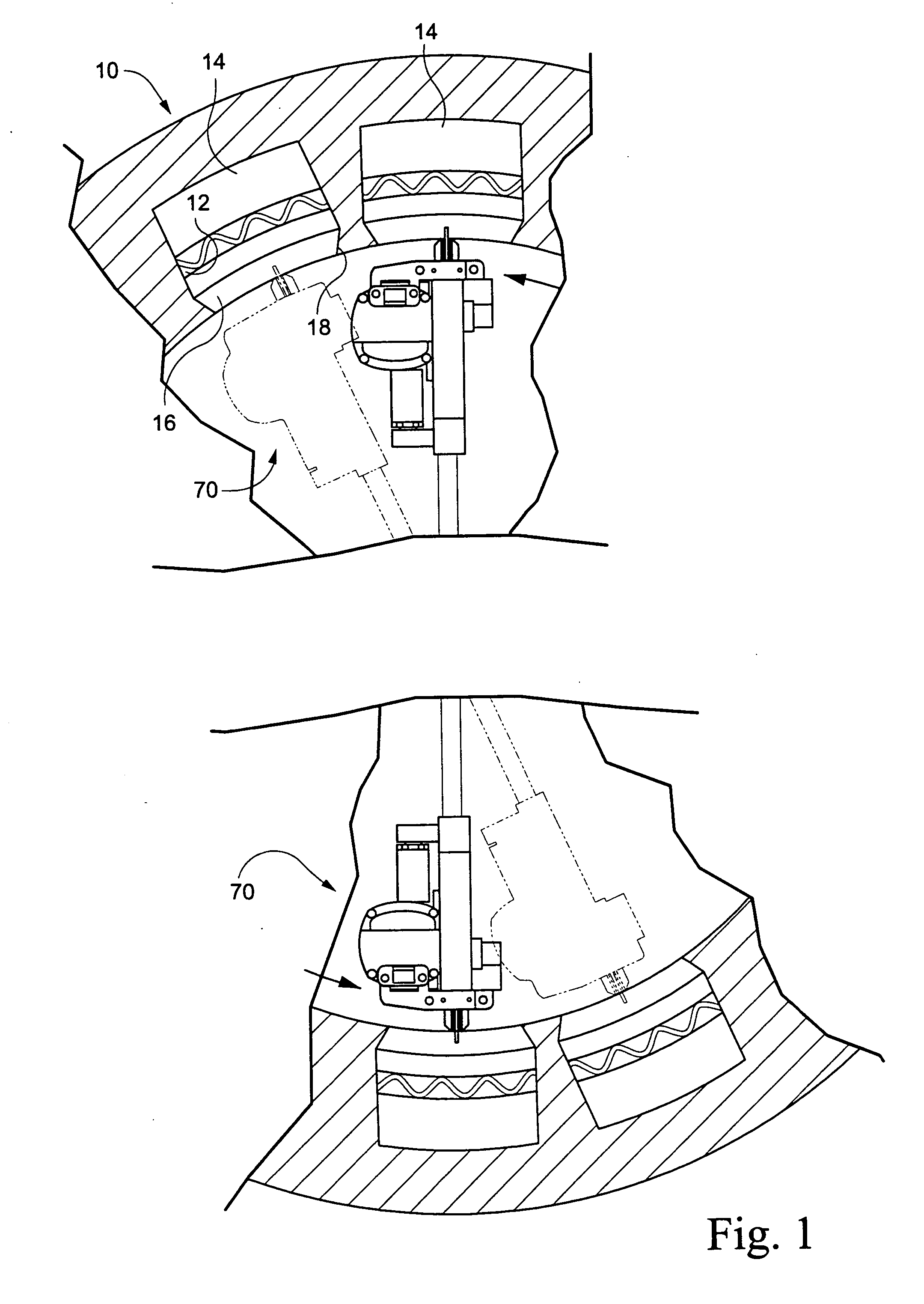
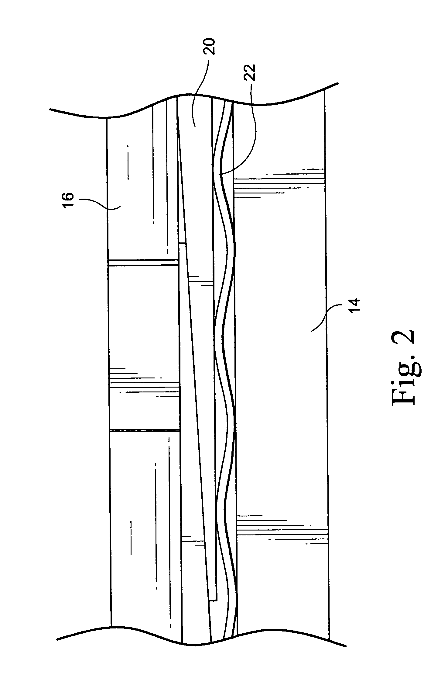
[0013] Referring now to the drawings, particularly to FIG. 1, there is illustrated a stator core generally designated 10 forming part of an electrical machine such as an electrical generator. The stator core 10 has a plurality of longitudinally extending slots 12 spaced circumferentially one from the other and opening in a radial inward direction. Windings 14 are disposed in the slots 12. As illustrated in FIGS. 1 and 2, the radially inwardly opening slots 12 are closed by wedges 16 which have tapered surfaces 18 for cooperation with complementary tapered surfaces along the length of the slots adjacent the radially inner opening of the slots to retain the windings within the slots 12. The undersurfaces of the wedges 16 are tapered as illustrated in FIG. 2 and tapered slides 20 underlie the wedges 16 to maintain the wedges 16 in the tapered or dovetail shaped groove of the slots. Ripple springs 22 underlie the slides 20 and lie between the slides 20 and the windings 14. The ripple sp...


PUM

PropertyMeasurementUnit
Forceaaaaaaaaaa

Abstract

The wedge removal apparatus includes an elongated frame having telescopic elements at opposite ends with cylinders to engage pads along opposite sides of the frame against diametrically opposed wedges of stator core slots. The frame mounts a linear drive assembly carrying a carriage for longitudinal movement relative to the drive assembly and frame. The carriage mounts diametrically opposed heads and a cylinder displaces the heads radially outwardly to engage the wedges and compress underlying ripple springs. Saws carried by the heads cut through the wedges as the carriage is displaced along the frame and without binding because of the force applied to the wedges compressing the ripple springs. The linear drive assembly is rotated to discrete circumferential positions to cut the wedges of additional diametrically opposed slots.

Description

BACKGROUND OF THE INVENTION [0001] The present invention relates to apparatus and methods for removing wedges overlying the windings of a stator core in an electrical machine and particularly relates to apparatus and methods for cutting the wedges longitudinally parallel to the slots to facilitate removal of the wedges and refurbishment of the machine. [0002] In electrical machines such as generators, the stator core has a slot wedging system for retaining the windings in the core. The windings are arranged in circumferentially spaced, longitudinally extending slots, which, along radially inward ends of the slots have dovetail or tapered surfaces. A plurality of wedges typically extend along the length of each circumferentially spaced slot to retain the windings in the slot. The radial outer sides of the wedges are tapered and tapered slides underlie the wedges, forcing the wedges radially inwardly against the dovetail slots. In recent electrical machine construction, ripple springs...

Claims


Application Information

Patent Timeline
IPC IPC(8): H02K15/14H02K15/00
CPCH02K3/487H02K15/0018Y10T29/5383Y10T29/49009Y10T29/53157Y10T29/53152Y10T29/53835Y10T29/53143
Inventor STEWART, GARY LINDSEYHATLEY, KENNETH JOHNHATLEY, RICHARD MICHAELMCDONNELL, SEAN MICHAELBOUSQUET, MICHAEL JOHNAPPLEGATE, FRANK HAROLD
Owner GENERAL ELECTRIC CO
Why Eureka
Try Eureka