Reshaping device with ejector and method of ejecting workpieces

a technology of ejector and ejector, which is applied in the direction of presses, brake systems, manufacturing tools, etc., can solve the problem of relatively high cost of active drive of such ejector pins

Inactive Publication Date: 2006-02-09
SCHULER PRESSEN GMBH & CO KG
View PDF4 Cites 13 Cited by
  • Summary
  • Abstract
  • Description
  • Claims
  • Application Information

AI Technical Summary

Benefits of technology

[0012] Preferably, at least one pressure storing cylinder is provided with a terminal-location damping arrangement. The terminal-location damping arrangement provides for a slowdown and soft braking of the piston of the pressure storing cylinder and thus for the braking of the hydraulic flow shortly before reaching the terminal position. In this manner the ejector discontinues its ejecting stroke gradually, rather than abruptly. As a result, a clean transfer of the workpiece between the ejector and the transferring device is made possible.

Problems solved by technology

The active drive of such ejecting pins is relatively expensive.

Method used


Image

  • Reshaping device with ejector and method of ejecting workpieces
  • Reshaping device with ejector and method of ejecting workpieces
  • Reshaping device with ejector and method of ejecting workpieces

Examples


Embodiment Construction

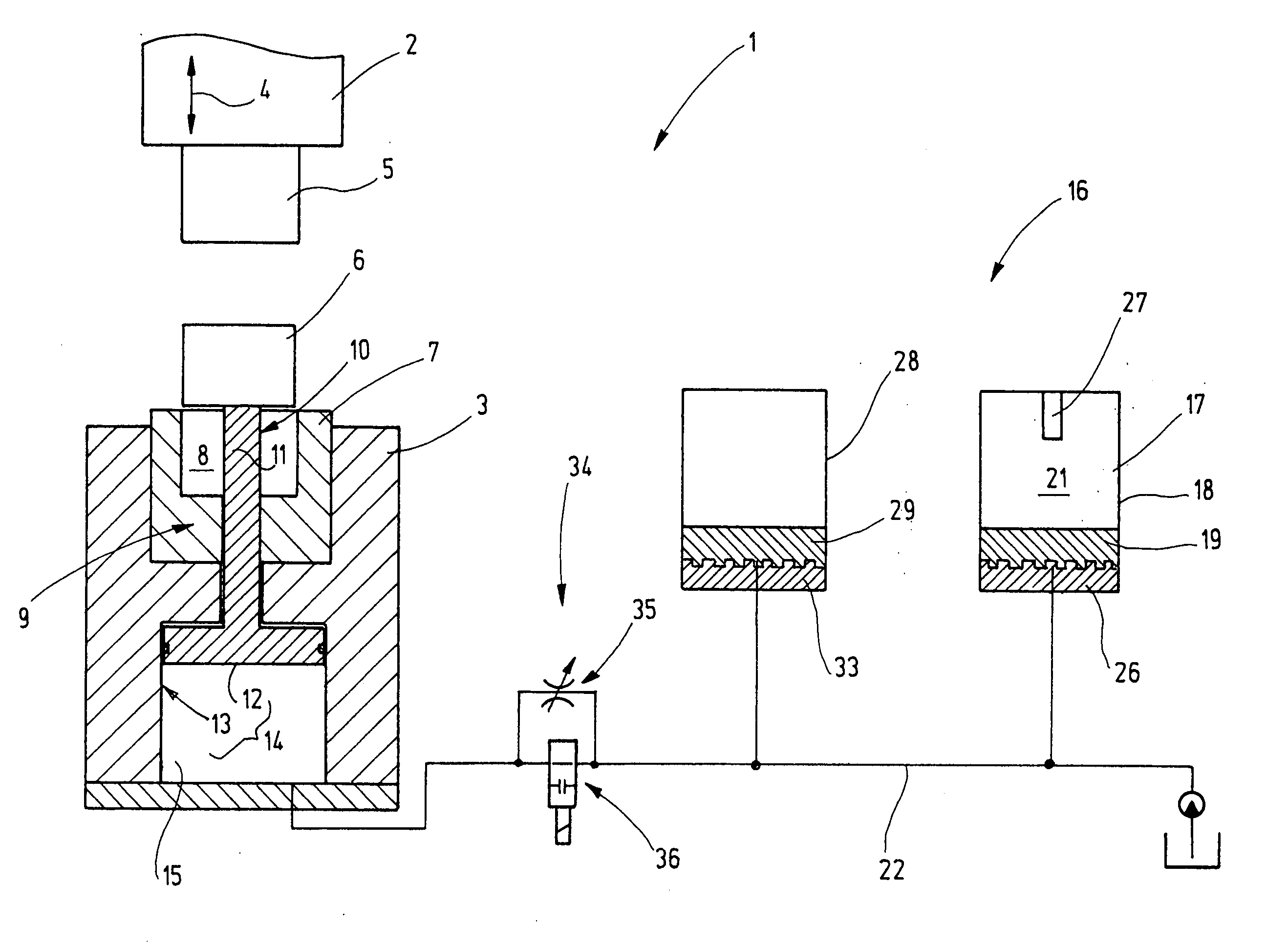
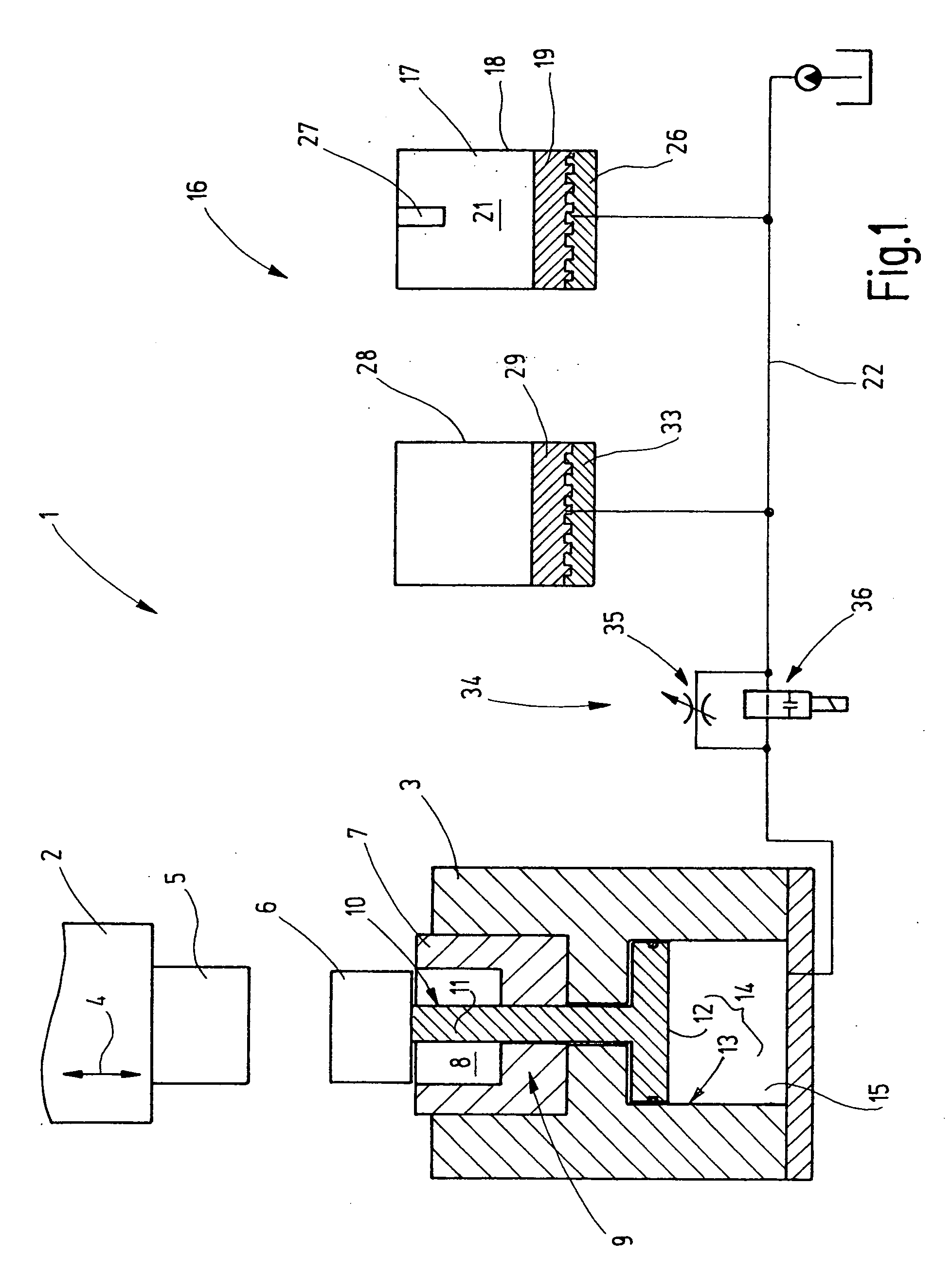
[0021]FIG. 1 schematically illustrates a reshaping device 1 which includes a press not shown in further detail. The press has a plunger 2 movable, for example, vertically up and down and a tool stand 3 stationarily supported in the press stand. The direction of motion of the plunger 2 is shown by an arrow 4 in FIG. 1. The plunger 2 carries a ram 5 for reshaping a workpiece 6 which is shown as a blank in FIG. 1.

[0022] In the tool stand 3 a matrix 7 is supported which may also be designated as a swage and which has an engraving 8 for reshaping the workpiece 6 therein.

[0023] The matrix 7 and the tool stand 3 are provided with an ejecting device 9 which has one or several ejectors. The ejectors may be in each instance formed as a movable matrix part 10, shaped, for example, as a slender cylinder. In the present embodiment the movable matrix part 10 is a cylinder pin 11 having a cylindrical circumferential surface and a planar end face. Particularly the shape of the end face may be arb...


PUM

PropertyMeasurementUnit
pressureaaaaaaaaaa
plunger movementaaaaaaaaaa
depthaaaaaaaaaa

Abstract

A reshaping device according to the invention has at least one ejector, for example, in the form of a cylinder pin (11) which is shifted by the workpiece (6) against the pressure from a pressure storing cylinder (17) or other suitable energy storing device before and/or during the reshaping of the workpiece (6). The workpiece ejection occurs by the work stored in the energy storing device.

Description

CROSS REFERENCE TO RELATED APPLICATION [0001] This application claims the priority of German Patent Application No. 10 2004 038 796.6, filed on Aug. 9, 2004, and of German Patent Application No. 10 2005 036 775.5, filed on Aug. 3, 2005, the subject matter of which, in its entirety, is incorporated herein by reference. FIELD OF THE INVENTION [0002] The invention relates to a reshaping device for reshaping, particularly for a massive reshaping, of workpieces and further relates to a method of ejecting workpieces from a matrix. BACKGROUND OF THE INVENTION [0003] Ejecting devices are known which form part of a reshaping tool. They are conventionally disposed in the lower tool and comprise one or more pins which are movable by mechanical or hydraulic drives. The ejecting devices serve for lifting the workpiece out of the lower tool subsequent to reshaping, so that the workpiece may be grasped and transported away by a transferring device. [0004] The active drive of such ejecting pins is ...

Claims


Application Information

Patent Timeline
Patent Type & Authority Applications(United States)
IPC IPC(8): B60T8/42
CPCB21J13/14B21J9/12
Inventor FAHRENBACH, JURGEN
Owner SCHULER PRESSEN GMBH & CO KG
Why Eureka
Try Eureka