

Antenna duplexer, and RF module and communication apparatus using the same
a technology of rf module and antenna duplexer, which is applied in the direction of impedence networks, electrical apparatus, and semiconductor devices having balanced terminals, can solve the problems of unbalanced type of transmission terminal and receiving terminal in the characteristics of the conventional antenna duplexer, which include an unbalanced type terminal, can not be directly connected to such an antenna duplexer, etc., to achieve superb receiving characteristics and transmission characteristics
- Summary
- Abstract
- Description
- Claims
- Application Information
AI Technical Summary
Benefits of technology
Problems solved by technology
Method used
Image

Examples
first embodiment
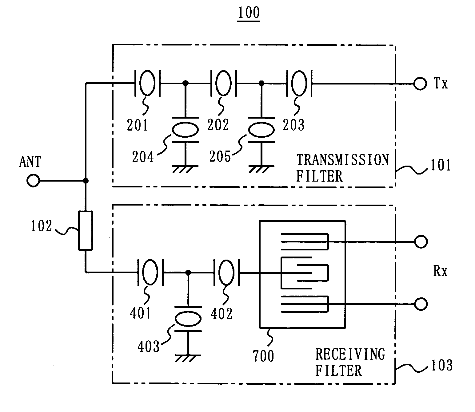
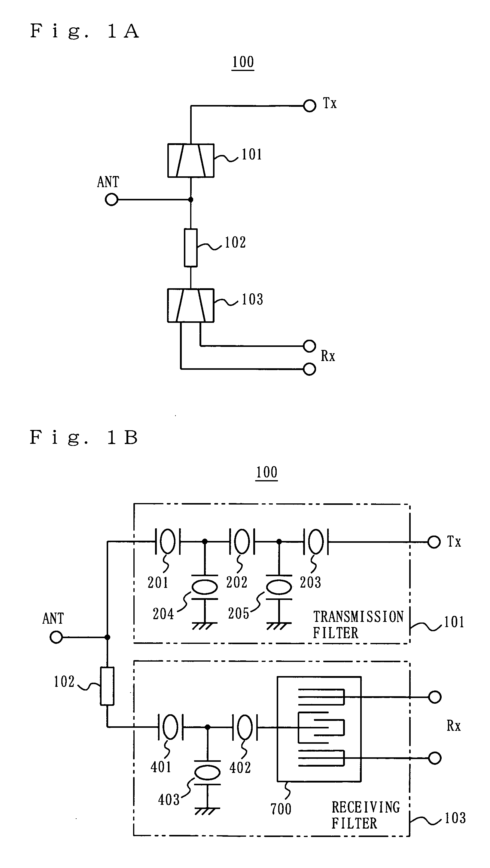
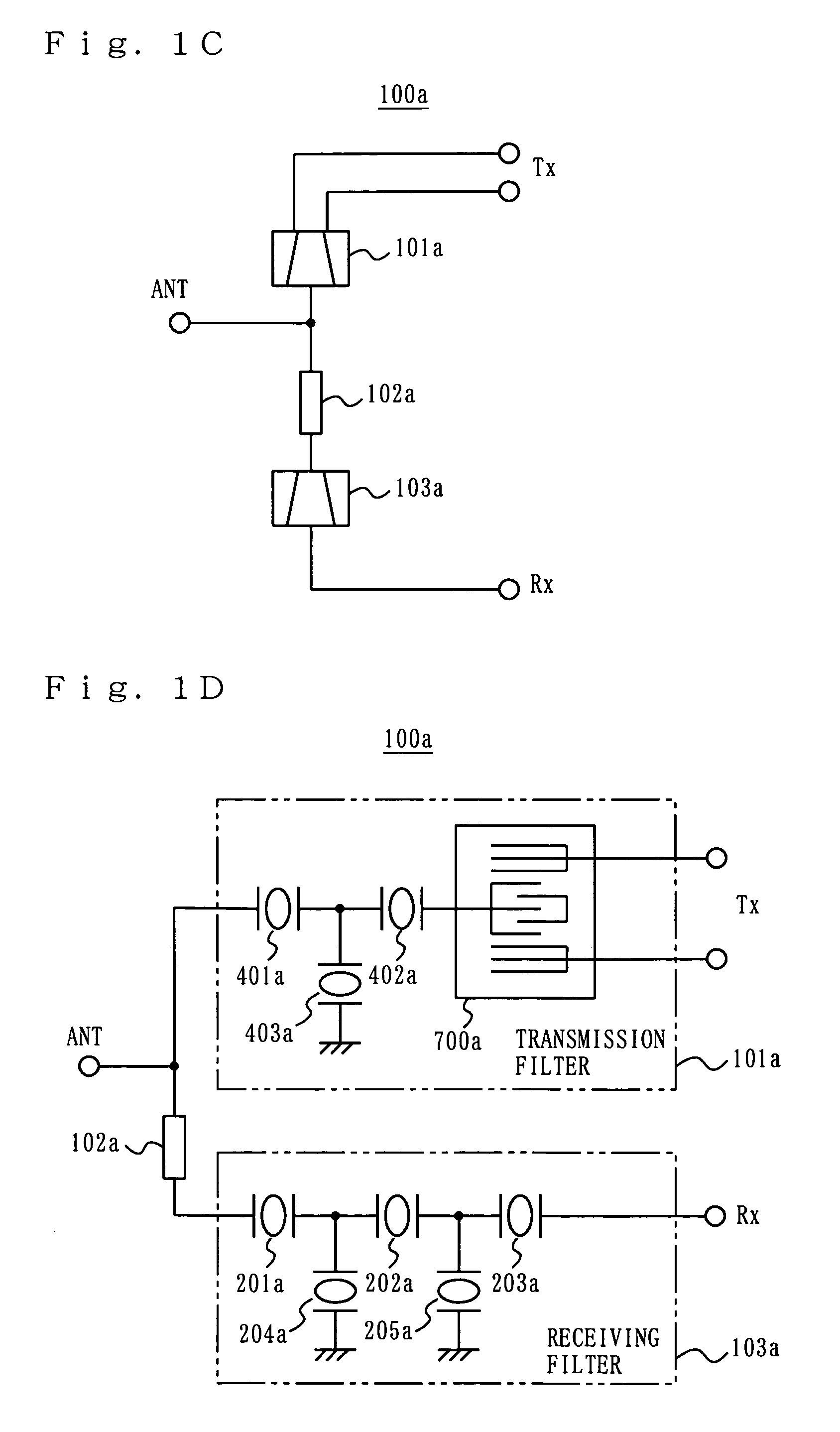
[0087]FIG. 1A is a block diagram showing a structure of an antenna duplexer 100 according to a first embodiment of the present invention. In FIG. 1A, the antenna duplexer 100 includes an antenna terminal ANT, a transmission terminal Tx, a receiving terminal Rx, a transmission filter 101, a phase shifter 102, and a receiving filter 103. The antenna terminal ANT is an unbalanced type terminal. The receiving terminal Rx is a balanced type terminal. The transmission terminal Tx is an unbalanced type terminal. The antenna terminal ANT is connected to the transmission terminal Tx via the transmission filter 101. The antenna terminal ANT is also connected to the receiving terminal Rx via the phase shifter 102 and the receiving filter 103. The receiving filter 103 has a balanced-unbalanced conversion function. Owing to this function, a received input signal (unbalanced signal) from the antenna terminal ANT, which is an unbalanced type terminal, is transmitted to the receiving terminal Rx as...
second embodiment
[0134]FIG. 11 shows a structure of an antenna duplexer 1100 according to a second embodiment of the present invention. In FIG. 11, the antenna duplexer 1100 includes a transmission filter 1102 and a receiving filter 1103 which are mounted on a mounting substrate 1101 by face-down bonding. The mounting substrate 1101 has lines, a phase shifter and external terminals (none is shown) built therein. The mounting substrate 1101 and the transmission filter 1102 are electrically connected to each other via bumps 1104a and 1104b, and the mounting substrate 1101 and the receiving filter 1103 are electrically connected to each other via bumps 1105a and 1105b. The transmission filter 1102 includes FBARs. The receiving filter 1103 includes a longitudinal mode coupled SAW filter. The transmission filter 1102 and the receiving filter 1103 are provided as separate chips. All the structures and modifications described in the first embodiment are also applicable to the transmission filter 1102 and t...
third embodiment
[0143]FIG. 13 shows a structure of an RF module 1300 according to a third embodiment of the present invention. In FIG. 13, identical elements to those shown in FIG. 12 will bear identical reference numerals thereto and descriptions thereof will be omitted. In FIG. 13, the RF module 1300 includes a transmission filter 1202 and a receiving filter 1203 which are mounted on a mounting substrate 1301 by face-down bonding. A semiconductor device 1304 is wire-bonded on the mounting substrate 1301. The mounting substrate 1301 has lines, a phase shifter and external terminals (none is shown) built therein. The mounting substrate 1301 and the transmission filter 1202 are electrically connected to each other via bumps 1204a and 1204b, and the mounting substrate 1301 and the receiving filter 1203 are electrically connected to each other via bumps 1205a and 1205b. The mounting substrate 1301 and the semiconductor device 1304 are electrically connected to each other via wires 1307a and 1307b. The...
PUM
 Abstract
Description
Claims
Application Information