Optical fiber microcoil, resonant structure and method of making the same

a technology of optical fiber and microcoils, which is applied in the field of optical fiber microcoils, resonant structure and method of making the same, can solve the problems of limiting the usefulness of such devices, many difficulties, and the inability of conventional etching processes to routinely form such smoothness, and achieves the effect of easy formation

Active Publication Date: 2007-09-04
FURAKAWA ELECTRIC NORTH AMERICA INC
View PDF12 Cites 27 Cited by
  • Summary
  • Abstract
  • Description
  • Claims
  • Application Information

AI Technical Summary

Benefits of technology

[0006]In accordance with one aspect of the present invention, a microfiber (i.e., a fiber drawn to a diameter on the order of one micron or less) is fabricated by utilizing a microfurnace in combination with laser heating to draw a fiber with transmission characteristics far superior to those formed using lithographic techniques. The fiber is inserted through the microfurnace (capillary tube) such that the section of the fiber to be heated and drawn remains in the microfurnace. The indirect heating of the fiber allows the use of a laser for heating a section of the capillary tube up to the glass melting temperature. Using the inventive technique, fibers with a diameter of less than 100 nm may be drawn.
[0008]In accordance with the present invention, if the diameter of the microfiber is comparable to the radiation wavelength and the pitch of the coil, then coupling between adjacent turns will occur and give rise to high-Q resonances. Advantageously, the process of forming the microfiber allows for biconical input / output tapers to be easily formed on either side of the coil, providing a conventional method for coupling light into and out of the microcoil.
[0009]Various aspects of the present invention include the ability to control the Q of the resonant structure through various means, such as by controlling the number of turns in the coil, the pitch of the turns, temperature of the coil, etc. In one embodiment, oscillation can be induced by allowing adjacent turns of the microcoil to touch each other.

Problems solved by technology

Many difficulties present themselves when conventional planar (two-dimensional) technology, such as etching, is used to fabricate such resonant devices.
In particular, the surfaces of such devices need to exhibit deviations on the order of a few nanometers to reduce scattering losses and conventional etching processes cannot routinely form such smoothness.
At times, however, these devices suffer from the problem of overpopulation of the resonant modes, limiting the usefulness of such devices.
Moreover, and from a more practical view, the ability to couple light into and out of such WGM devices is extremely difficult to achieve and almost impossible to replicate for manufacturability purposes.

Method used


Image

  • Optical fiber microcoil, resonant structure and method of making the same
  • Optical fiber microcoil, resonant structure and method of making the same
  • Optical fiber microcoil, resonant structure and method of making the same

Examples


Embodiment Construction

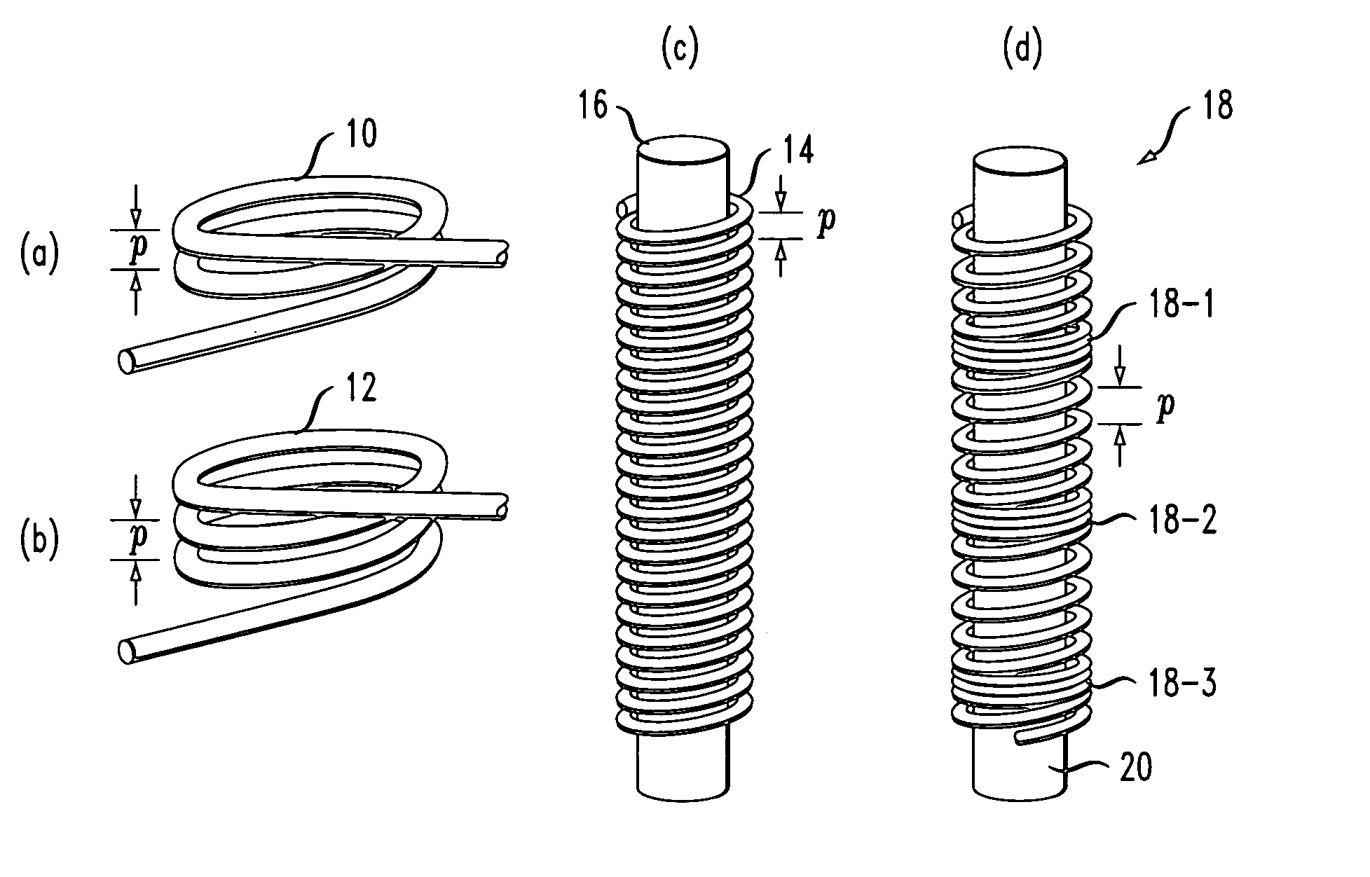
[0022]The present invention, as will be described in detail below, proposes the use of a coiled single mode optical microfiber (for the purposes of the present invention, the term “microfiber” is defined as a fiber with a diameter on the order of one micron, or less than (or on the order of) the wavelength of the electromagnetic field), as illustrated in FIGS. 1(a)-(d), to achieve self-coupling between turns, rather that using a closed loop optical path as in prior art arrangements. In one embodiment, the inventive microfiber coil can be wound around a cylindrical core (e.g., an optical fiber with larger diameter) wound into a self-touching loop, or be formed as a ring node, as in the prior art. The ideal microfiber “coil only” structure, such as those illustrated in FIGS. 1(a) and (b), can be created if the refractive index of the cylindrical core is low enough and matches the refractive index of the environment.

[0023]FIG. 1 illustrates four exemplary microfiber coils (also referre...


PUM

PropertyMeasurementUnit
inner diameteraaaaaaaaaa
diameteraaaaaaaaaa
diameteraaaaaaaaaa

Abstract

An optical fiber coil of sub-micron diameter is shown to exhibit self-coupling between adjacent turns so as to form a three-dimensional optical resonator of relatively low loss and high Q. As long as the pitch of the coil and propagating wavelength remain on the same order (or less than) the fiber diameter, resonance may occur. Resonances can be induced by allowing adjacent turns of the coil to touch each other. Optical devices such as resonators and interferometers may then be formed from such “microcoils” that exhibit superior characteristics to conventional planar devices. A method of forming such a microfiber using indirect laser heating is also disclosed.

Description

CROSS REFERENCE TO RELATED APPLICATION[0001]This application claims the benefit of Provisional Application Ser. No. 60 / 555,994, filed Mar. 24, 2004.TECHNICAL FIELD[0002]The present invention is related to the formation of microfibers (i.e., fibers having a diameter on the order of one micron or less) and, more particularly, to the utilization of such fibers as three-dimensional, coiled optical devices such as resonators and interferometers (fiber microcoils).BACKGROUND OF THE INVENTION[0003]A substantial amount of research is currently on-going in the field of optical micro-cavity physics, particularly directed at the ability to develop a high-Q cavity resonator. In general, resonant cavities that can store and re-circulate electromagnetic energy at optical frequencies have many useful applications, including high-precision spectroscopy, signal processing, sensing and filtering. Many difficulties present themselves when conventional planar (two-dimensional) technology, such as etchi...

Claims


Application Information

Patent Timeline
Patent Type & Authority Patents(United States)
IPC IPC(8): G02B6/00C03B37/023H01S3/00
CPCB82Y20/00C03B23/043G02B6/107G02B6/2934G02B6/29343
Inventor SUMETSKY, MIKHAIL
Owner FURAKAWA ELECTRIC NORTH AMERICA INC
Why Eureka
Try Eureka