Cable binding band structure

Inactive Publication Date: 2006-02-16
TAIWAN PAIHO LTD
View PDF4 Cites 53 Cited by
  • Summary
  • Abstract
  • Description
  • Claims
  • Application Information

AI Technical Summary

Benefits of technology

[0006] It is, therefore, the primary purpose of the present invention to provide a cable binding band structure, including a binding band made up of a fleeced stick side and a fastening hook side with a plurality of protrusive fastener dots distributed thereon wherein both ends of the binding band are respectively defined by a retaining section and a binding section, and a through hole is properly disposed at a preset position of the binding band thereon for the retaining sec

Problems solved by technology

There are some drawbacks to such conventional cable binding band structure.
As a result, the cable 10 must be awkwardly wound around and bundled up according to the position of the binding tie 12, which is quite inconvenient and limited in practical use.
Second, the binding tie 12, fixedly attached to the plug 11 of the cable 10, must be discarded

Method used


Image

  • Cable binding band structure
  • Cable binding band structure
  • Cable binding band structure

Examples


Embodiment Construction

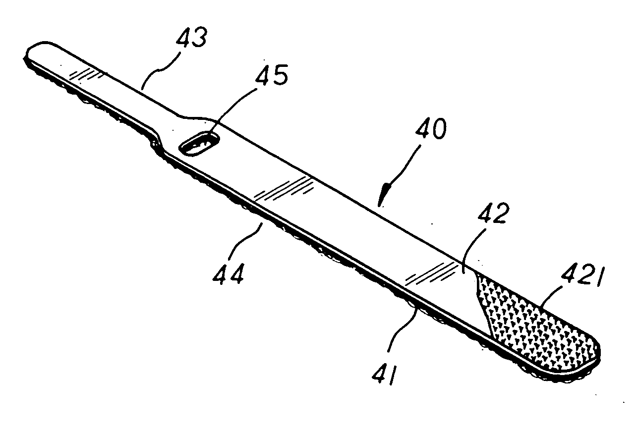
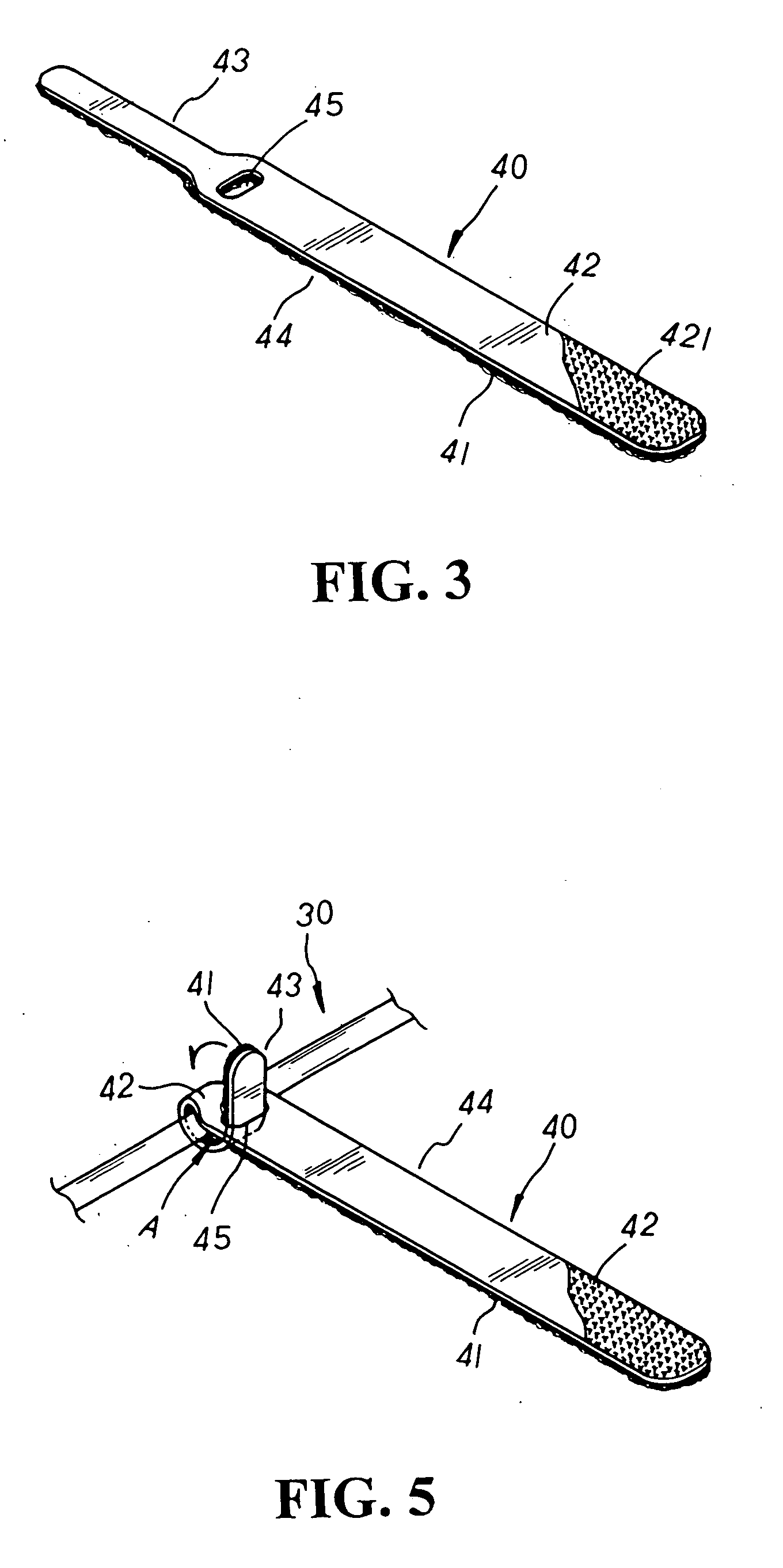
[0016] Please refer to FIGS. 3 to 4 inclusive. The present invention is related to a cable binding band structure, including a binding band 40 made up of a fleeced stick side 41 and a fastening hook side 42 with a plurality of protrusive fastener dots 421 distributed thereon as shown in FIG. 4. Both ends of the binding band 40 thereof are respectively defined by a narrowed retaining section 43 and a wide binding section 44, and the binding section 44 thereof has a through hole 45 properly disposed at a preset position thereon in matched cooperation with the retaining section 43 thereof.

[0017] Please refer to FIGS. 5 to 6 inclusive. In practical use, the retaining section 43 of the binding band 40 is directly wound around a cable 30 and inserted through the through hole 45 of the binding section 44 thereof. Then, the retaining section 43 protruding outside the through hole 45 thereof keeps winding downwards till the fleeced stick side 41 disposed at one surface of the binding band 4...


PUM


Abstract

A cable binding band structure includes a binding band made up of a fleeced stick side and a fastening hook side with a plurality of protrusive fastener dots distributed thereon wherein both ends of the binding band are respectively defined by a narrowed retaining section and a wide binding section having a through hole properly disposed at a preset position thereon for the retaining section winding around the outer periphery of a cable to thread there-through with a movable binding loop formed thereby so as to attach the binding band onto the cable thereof. In practical use, the binding band can be freely moved along the cable to wrap up and collect the bundle of the cable in a convenient and speedy manner without the cable being awkwardly limited by the position of the binding band thereof. Besides, the binding band can be easily released from the cable without being cut off and economically reapplied onto another cable, efficiently providing a reusable and eco-friendly binding band thereof.

Description

BACKGROUND OF THE INVENTION [0001] The present invention is related to a cable binding band structure, including a binding band made up of a fleeced stick side and a fastening hook side with a plurality of protrusive fastener dots distributed thereon wherein both ends of the binding band are respectively defined by a narrowed retaining section and a wide binding section having a through hole properly disposed at a preset position thereon for the retaining section winding around a cable to thread there-through so as to attach the binding band onto the cable thereof. In practical use, the binding band can be freely moved to bundle up the cable in a convenient and speedy manner without the cable being awkwardly limited by the position of the binding band thereof. Besides, the binding band can be easily released from the cable without being cut off and economically reapplied onto another cable, efficiently providing a reusable and eco-friendly binding band thereof. [0002] Please refer t...

Claims


Application Information

Patent Timeline
IPC IPC(8): B65D63/00F16L3/08F16L3/23F16L3/233
CPCF16L3/23Y10T24/2708F16L3/233H02G3/32
Inventor CHENG, SEN-MEI
Owner TAIWAN PAIHO LTD
Why Eureka
Try Eureka