Magnetic tape cartridge

a technology of magnetic tape and tape drive, which is applied in the field of magnetic tape cartridges, can solve the problems of increasing the increase of achieve the effects of reducing the cost of the reader, and reducing the manufacturing cost of the tape driv

a technology of magnetic tape and tape drive, which is applied in the field of magnetic tape cartridges, can solve the problems of increasing the increase of achieve the effects of reducing the cost of the reader, and reducing the manufacturing cost of the tape driv

US20060032961A1Inactive Publication Date: 2006-02-16HITACHT MAXELL LTD

Image

  • Magnetic tape cartridge
  • Magnetic tape cartridge
  • Magnetic tape cartridge

Examples


first embodiment

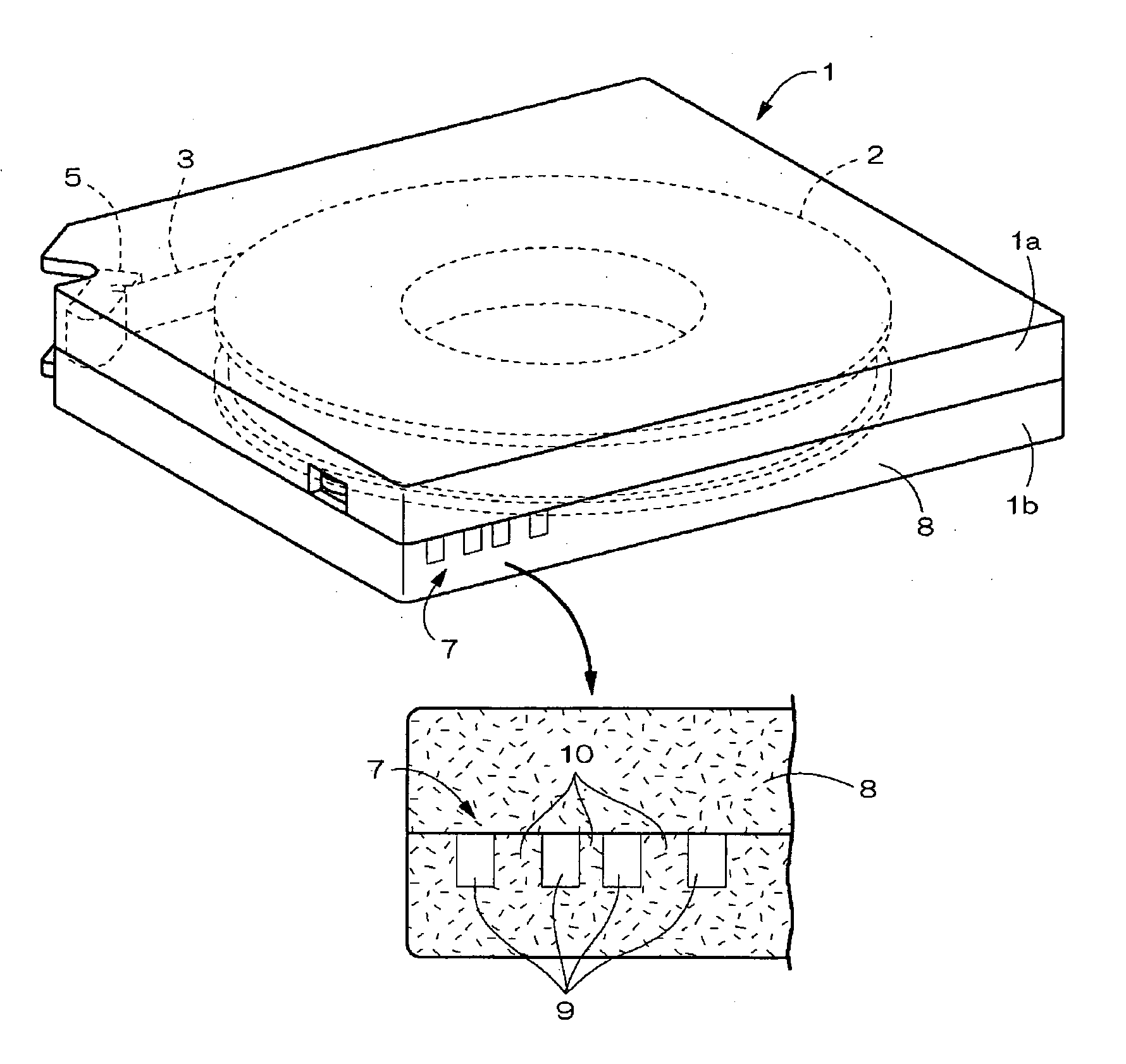
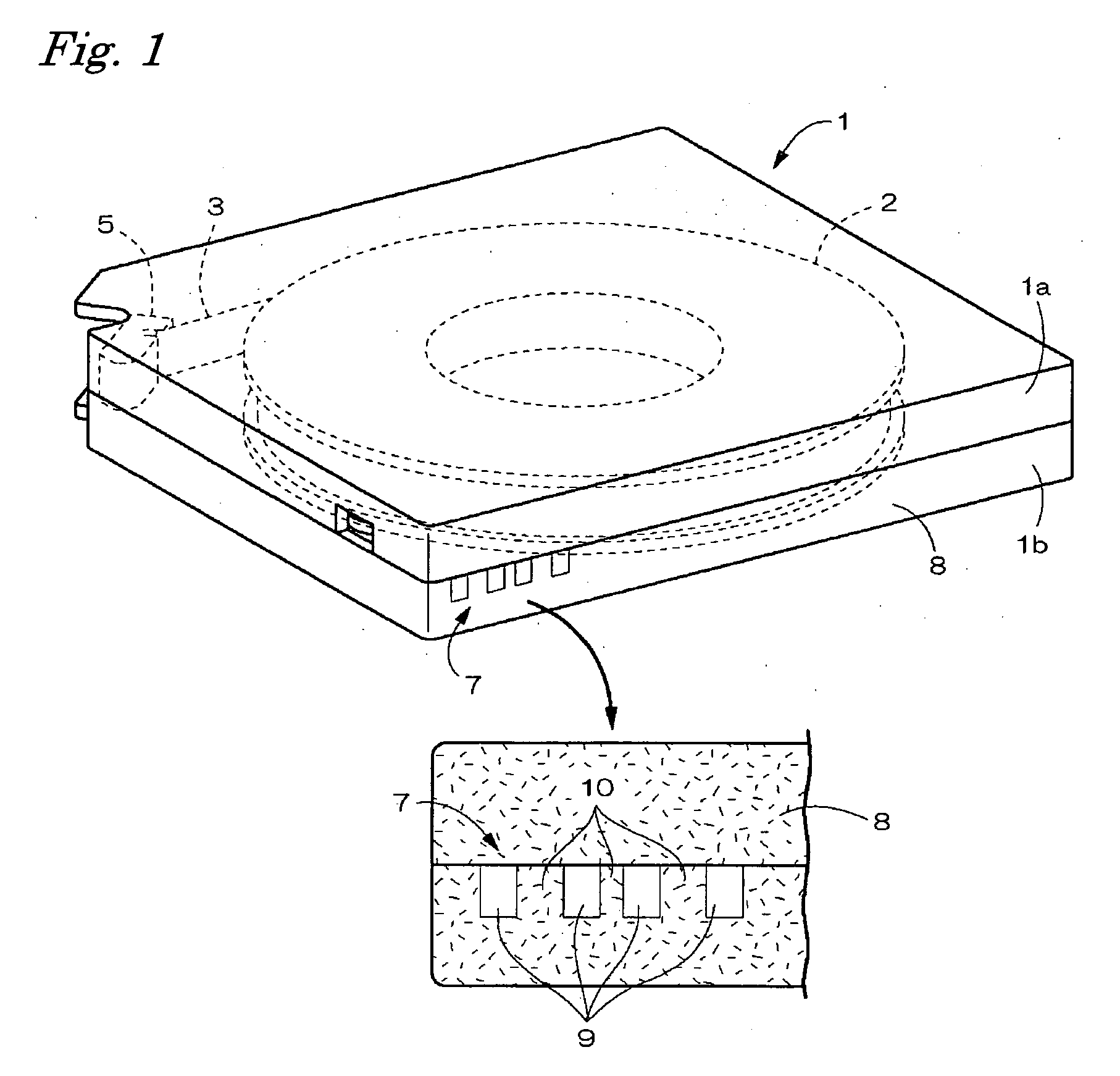
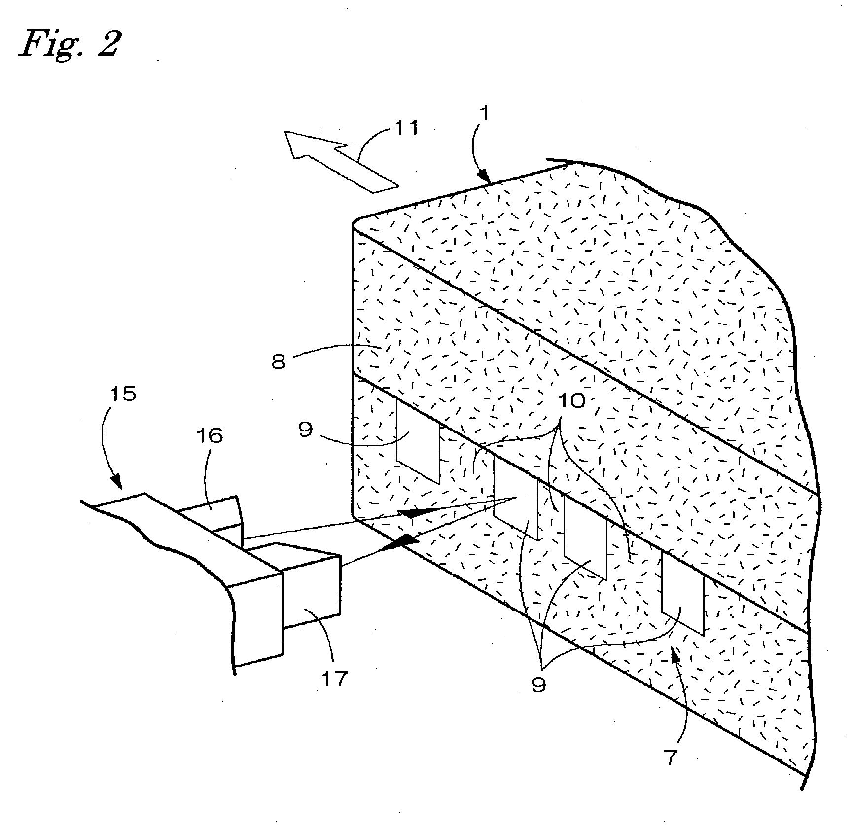
[0019]FIG. 1 through FIG. 3 show a first embodiment in which a magnetic tape cartridge according to the present invention is applied for computer data backup. As shown in FIG. 1 and FIG. 3, the magnetic tape cartridge has a box-shaped main case 1 formed by combining plastic upper and lower cases 1a and 1b so as to face each other. Inside the main case 1, a single reel 2 is disposed, and a tape (magnetic tape) 3 for recording data signals is wound around the reel 2. There is shown a reader pin 5 which is connected to a tape supply end and is caught by coupling means on the tape drive side. When the magnetic tape cartridge is loaded onto the tape drive D, the tape 3 is pulled to the outer front side of the main case 1 via the reader pin 5.

[0020] As shown in FIG. 1 through FIG. 3, an identification indicator 7 for identifying type information peculiar to the cartridge including tape characteristics and a tape standard of the tape 3 on the tape drive D side is provided on the right-and...

second embodiment

[0025] A second embodiment of the magnetic tape cartridge according to the present invention is shown in FIG. 4 and FIG. 5. As shown in FIG. 4, the magnetic tape cartridge has a box-shaped main case 1 formed by combining plastic upper and lower cases 1a and 1b so as to face each other. Inside the main case 1, a single reel 2 is disposed, and a tape (magnetic tape) 3 for recording data signals is wound around the reel 2.

[0026] The reel 2 is a plastic molding composed of: a bottomed cylinder-shape hub 20 having a round cylinder wall 20a, a bottom wall 20b and an openable upper face; an upper flange 21 molded integrally with an upper outer periphery of the hub 20 in a protruding state; and a disc-shaped lower flange 22 welded to a lower outer periphery of the hub 20.

[0027] In order to prevent the reel 2 from turning over during off-periods of operation, a means to press and bias the reel 2 toward the bottom wall of the case is provided in the hub 20. The biasing means includes a comp...


PUM

PropertyMeasurementUnit
magneticaaaaaaaaaa
optical readeraaaaaaaaaa
light reflectanceaaaaaaaaaa

Abstract

A tape cartridge capable of reliably identifying difference in type among tape cartridges without causing a tape drive side to have increased costs is provided. On the outer surface of a main case, an identification indicator is formed in a stripe shape having a grain printed portion and a mirror surface portion arranged alternately toward a loading direction of a magnetic tape cartridge onto a tape drive. An indicator format of the identification indicator on the magnetic tape cartridge, which is displaced and moved in the loading direction when loading operation of the magnetic tape cartridge onto the tape drive is conducted, is read by an optical reader mounted on the tape drive. This makes it possible to obtain type information on the magnetic tape cartridge on the tape drive side.

Description

BACKGROUND OF THE INVENTION [0001] The present invention relates to a magnetic tape cartridge having an identification indicator for identifying type information peculiar to the cartridge including tape characteristics and a tape standard of the magnetic tape on the tape drive side. [0002] It is publicly known, as shown in Patent Documents of JP 2002-373479 A (FIG. 1, FIG. 2) and JP 2002-367336 A (FIG. 1, FIG. 2) for example, that in the field of magnetic tape cartridges, an identification indicator which can be read by an optical reader mounted on the tape drive side is provided on the outer surface of the main case. In the Patent Documents, a two-dimensional code as an identification display is formed on the outer surface of the main case. [0003] The two-dimensional codes can carry data with a data size several dozen to several hundred times larger than the data size of bar codes, and therefore according to the tape cartridges in the Patent Documents, ample information can be tran...

Claims


Application Information

Patent Timeline
16 Feb 2006
Publication
US20060032961A1
IPC
G11B23/107
CPC
G11B23/042; Y10S242/912; G11B23/048; G11B23/044
Inventors
BAN, KEIJI