High speed data interface to the AC power line through a standard light bulb socket

a technology of ac power line and light bulb socket, which is applied in the direction of data switching networks, instruments, lighting support devices, etc., can solve the problems of difficult and expensive installation of such wiring, the device necessary for interfacing consumer products with the ac power line has only been developed to a limited degree, and the class of devices that are not well-adapted to this particular line cord and plug/receptacle interfa

Active Publication Date: 2006-02-16
GENERAL WIRELESS OPERATIONS +1
View PDF6 Cites 27 Cited by
  • Summary
  • Abstract
  • Description
  • Claims
  • Application Information

AI Technical Summary

Benefits of technology

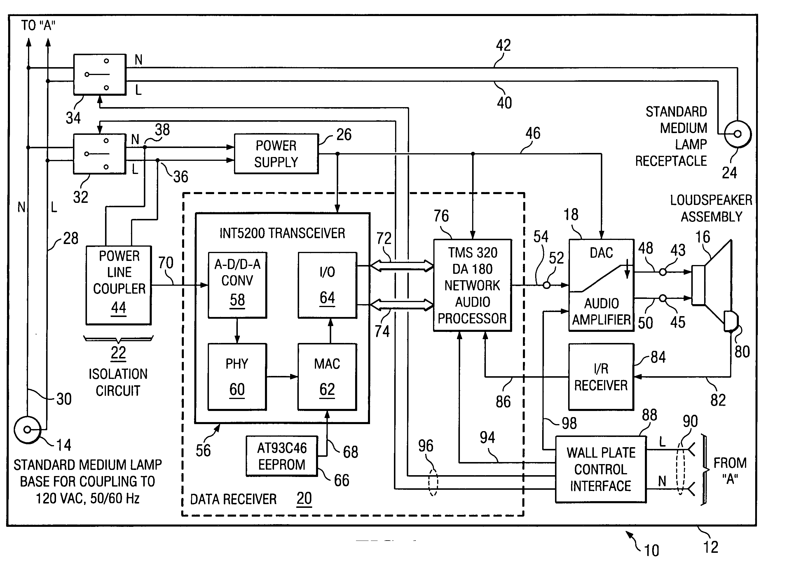
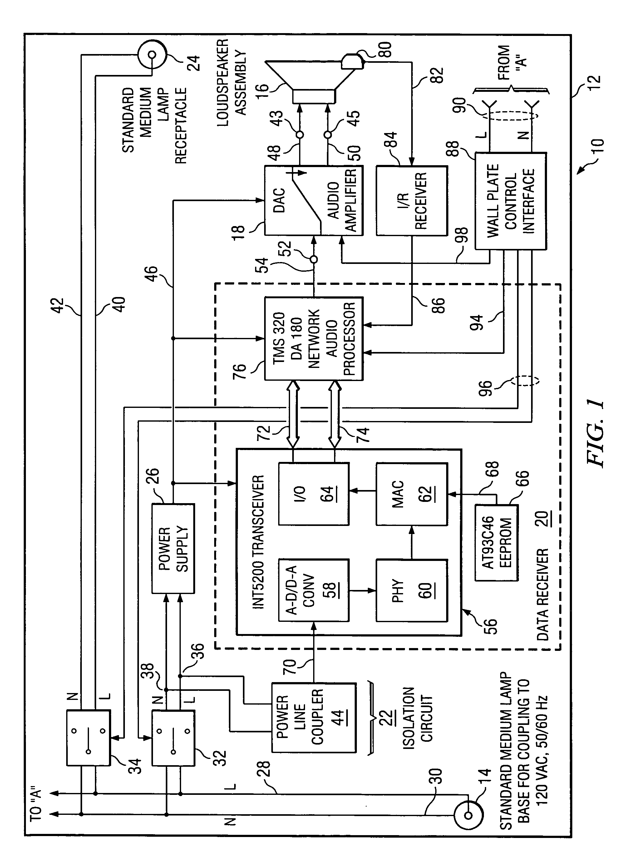
[0014] In one embodiment, the electrical device is a loudspeaker (or other transducer) which is fed audio (or other) signals by an amplifier (or other device) supported on the loudspeaker (or transducer) frame. The audio (or other) signals are decoded from high speed data obtained from the output of a HomePlug® receiver which receives and demodulates the audio (o...

Problems solved by technology

However, the apparatus necessary for interfacing consumer products with the AC power line has only been developed to a limited degree.
However, there is another class of devices that are not well-adapted to this particular line cord and plug/receptacle interface, that may be mounted in a ceiling or on a wall near the ceiling or in which a line cord is not supplied.
Installation of such wiring is often a difficult and expensive task that typically requires the skills of an electrician to install the wiring properly, safely, and to accommodate local building codes.
As a result, to avoid the cost and inconvenience, speakers may often be installed by non-electricians ...

Method used


Image

  • High speed data interface to the AC power line through a standard light bulb socket
  • High speed data interface to the AC power line through a standard light bulb socket
  • High speed data interface to the AC power line through a standard light bulb socket

Examples


Embodiment Construction

[0020] In the detailed description which follows, the term “high speed” data will be taken to mean digital data transmitted at a relatively high data rate. Data rate is measured in bits per second. For example, a data rate of 10 million bits per second is usually expressed as 10 M bps. High speed data transfer in power line communications in currently available technologies is typically in the range of one to twenty Mbps. Technologies under development are pushing this range to 50 and 100 Mbps and beyond. In the exemplary embodiment to be described using the HomePlug® 1.0 technology, the maximum data rate is 14 Mbps. However, other versions of this technology, such as HomePlug AV (for audio-video), operating at data rates up to 60 Mbps and higher may soon be available. As compared with CCITT Group 3 or Group 4 facsimile transmission or the modems typically used for personal computers before the widespread availability of digital subscriber lines (DSL), for example, which operated at...


PUM


Abstract

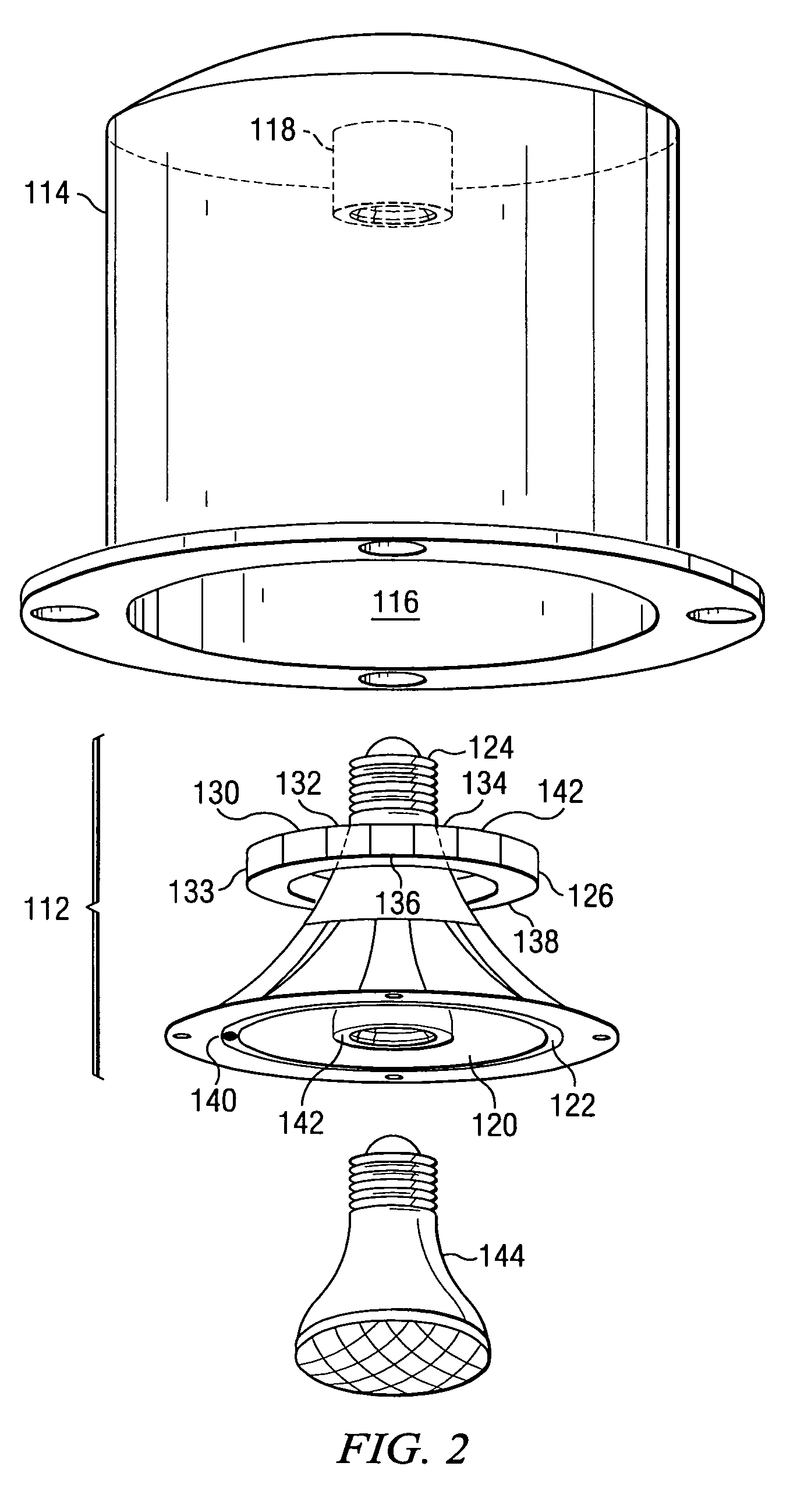
There is disclosed a data receiving device for coupling to an AC power line through a standard light bulb socket. A standard medium lamp base is supported by a frame and connected to a branch circuit of the AC power line. An electrical device having signal terminals and supported by the frame is driven by electrical circuitry having a first input and a first output. The first output is coupled to the signal terminals for driving the electrical device. A data receiver has a second input for receiving both AC power and a data signal from the AC power line. The second input is coupled to the lamp base and a second output is coupled to the first input of the electrical circuitry. In another aspect, a data interface comprising a standard medium lamp base coupled to a data terminal device having a data receiving and/or transmitting interface circuit therein is threadably engaged to a standard medium lamp receptacle connected to the AC power line branch circuit. The data receiving and/or transmitting interface circuit, or data modem, in the data terminal device is configured for extracting data encoded for transmission or encoding data to be embedded and transmitted along the AC power line branch circuit.

Description

CROSS-REFERENCE TO RELATED APPLICATION [0001] The present U.S. patent application claims priority from earlier filed U.S. Provisional Patent Application Ser. No. 60 / 601,074, filed Aug. 12, 2004 and entitled “High Speed Data Interface To The AC Power Line Through A Standard Light Bulb Socket.”BACKGROUND OF THE INVENTION [0002] 1. Field of the Invention [0003] The present invention generally relates to high speed data communication via the AC power line and, more particularly, to providing access to a high speed data communications network on the AC power line through a standard light bulb socket or receptacle. [0004] 2. Background and Description of the Prior Art [0005] The development of the technology for high speed or broadband data communication on the AC power line has advanced to the point where it is readily available for use in and with consumer products that can be installed and used without having to install wiring and without having to rely on batteries as a source of powe...

Claims


Application Information

Patent Timeline
IPC IPC(8): H05B37/02
CPCF21V33/0056H04L12/2803H05B37/0263H04L2012/2843H04L12/2838H05B47/185
Inventor MATHEWS, DAVID K.GRIFFIN, ALFRED C.
Owner GENERAL WIRELESS OPERATIONS
Why Eureka
Try Eureka