Scanless virtual retinal display system

a virtual retina and display system technology, applied in semiconductor lasers, applications, instruments, etc., can solve the problems of reducing the degree to which a viewer is rendered effectively blind to the real world, reducing the effectiveness of the illusion of being immersed in the displayed world, and reducing the degree of lag time, so as to reduce lag time, reduce lag time, and eliminate lag

Inactive Publication Date: 2006-02-16
CARESTREAM HEALTH INC
View PDF24 Cites 63 Cited by
  • Summary
  • Abstract
  • Description
  • Claims
  • Application Information

AI Technical Summary

Problems solved by technology

The HMD has a number of limitations, most prominent of which is the manner in which the viewer's head in blindly encased within a helmet.
Removal of the helmet and wearing the display as glasses exchanges the intrusion of the helmet for intrusiveness of the real world upon viewer—still reducing the effectiveness of the illusion of being immersed in the displayed world.
This exchanged of one form of intrusion for another only slightly reduces the degree to which a viewer rendered effectively blind to the real world.
In all cases of virtual reality displays (with exception of those that create a virtual exit pupil), since a display in located in close proximity to the eye, the viewer suffers problems resulting from the dissociation of eye vergance (where objects seem some distance from the observer) from accommodation (where the eye is forced to stretch the macula to focus on a screen in close proximity in order to focus the image onto the retina.)
This created new problems and challenges in the form of finding a means of scanning extremely small images onto the retina (essentially treating the retina like a micro-cathode of a television and substituting a laser for electron beam).
All the display solutions continue to be limited by the concept of creating images by scanning, that is by changing the elements of the image in a spatially and temporally sequential manner.

Method used


Image

  • Scanless virtual retinal display system
  • Scanless virtual retinal display system
  • Scanless virtual retinal display system

Examples


Embodiment Construction

[0064] The present invention is a virtual retinal display system that addresses the preceding problems by using an array of lasers. Each laser in such an array being addressable individually and in parallel (rather than sequentially) in time and location, thus creating a scanless virtual retinal display. The lasers in the array having qualities typical—and currently unique to—organic VCSEL devices, also herein referred to as organic laser cavity devices and used interchangeably—each such laser requiring extremely low levels of incoherent light as a pump source, easy formation into arrays of non-planar shape, and having both low power and small size which are appealing to display devices that will be used to scan onto the retina. Such a VCSEL is described in U.S. Pat. No. 6,658,037 B2 (Keith B. Kahen et al.)

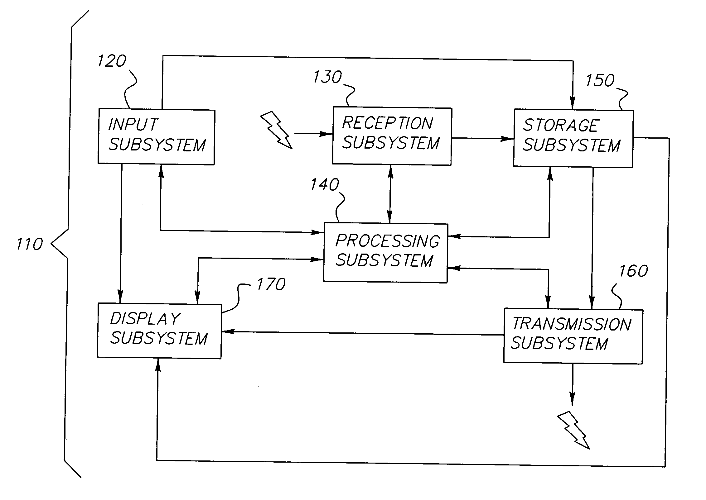
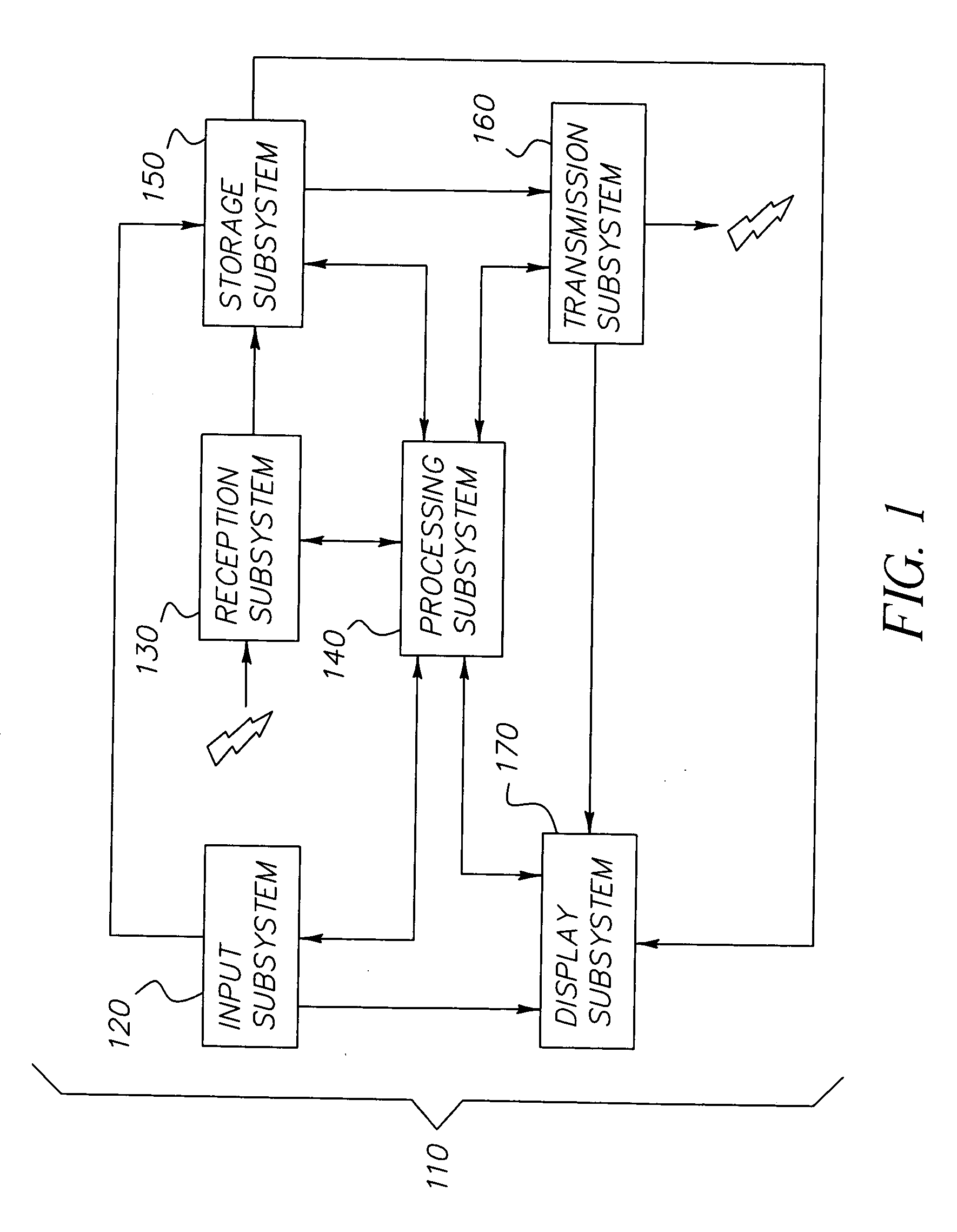
[0065] Referring to FIG. 1, the scanless retinal display system 110 is composed of subsystems typical and familiar to those versed in the art of assembling immersive display syst...


PUM


Abstract

A scanless display system that projects an image directly onto a retina, comprising a plurality of organic laser cavity devices. The organic laser cavity devices are placed in close proximity to a user's eye, for variably changing individual image pixels; wherein projecting the image directly onto the retina occurs by variably addressing individual image pixel locations and variably changing duration of illumination on individual image pixels upon the retina. Also included are a receiver for receiving transmitted electrical signals that include content information; a decoder for decoding received electrical signals; and a modulator for driving the scanless display under predetermined parameters.

Description

FIELD OF THE INVENTION [0001] The invention relates generally to the field of photonic emitter arrays. Specifically, the invention applies a novel refresh system to the area of display systems, and in particular to VRD (Virtual Retinal Display) systems. Additionally, the invention defines a display system that uses individually addressable lasers in an array, those lasers having features typical of VCSELs (Vertical Cavity Surface Lasers) as well as micro-lenses, sensors and other components appropriate to interactive graphics displays. BACKGROUND OF THE INVENTION [0002] There has been a constant effort to use technology to substitute images for reality. Since the Renaissance inventions of perspective and trompe l'oeil to the present day's “virtual reality,” there has been a constant effort to find ways to convince the viewer that an image of an object is the object itself. [0003] Great strides were made by Dr. Thomas Furness inventor of the head mounted display (HMD). The HMD, altho...

Claims


Application Information

Patent Timeline
Patent Type & Authority Applications(United States)
IPC IPC(8): A61B3/10
CPCG02B27/017G02B2027/0138G02B2027/014G02B2027/0187H01S5/423H01S5/041H01S5/183H01S5/18383H01S5/36G09G3/002
Inventor COVANNON, EDWARDMANICO, JOSEPH A.SPOONHOWER, JOHN P.PATTON, DAVID L.
Owner CARESTREAM HEALTH INC
Why Eureka
Try Eureka