Distortion compensation in an acoustic echo canceler

a technology of distortion compensation and canceller, which is applied in the field of telephony and televideo conferencing, can solve the problems of many inherent in half-duplex systems, remote terminals hearing echoes, and loudspeakers emitting undesirable sounds

Inactive Publication Date: 2006-02-16
CISCO TECH INC
View PDF5 Cites 27 Cited by
  • Summary
  • Abstract
  • Description
  • Claims
  • Application Information

AI Technical Summary

Problems solved by technology

This feedback can cause the loudspeaker to emit an undesirable “howling” noise and cause the remote terminals to hear echoes.
Half-duplex systems have many inherent problems, not the least of which is that a slight noise may unintentionally cause the loudspeaker to cut out.
As a result, it is often difficult to conduct a normal conversation with a system using half-duplex switching.
A problem with the above approach is that the loudspeakers do not produce sound pressure signals that are exactly proportional to the driving voltage (or current).
There may also be other sources of distortion within the sound system, such as amplifiers, analog-to-digital (A / D) and digital-to-analog (D / A) converters, and perhaps even the user's environment.
Existing AEC systems do not accurately remove the nonlinear components of the returned signal due to these sources of potential distortion.
As a result, a badly distorted form of the echo can pass through the echo cancellation process.
Another undesirable effect of these introduced distortions is that the adaptation of the AEC parameters is degraded, leading to a greater perceived echo.
However, reducing the adaptation rate has the undesirable effect of slowing the system's response to a changing acoustic environment such as when users are in motion and / or the room temperature fluctuates.
This solution, however, carries with it considerable expense and places severe limitations on the designs of the equipment.
High-quality loudspeakers are typically large and heavy and generate strong external magnetic fields.

Method used


Image

  • Distortion compensation in an acoustic echo canceler
  • Distortion compensation in an acoustic echo canceler
  • Distortion compensation in an acoustic echo canceler

Examples


Embodiment Construction

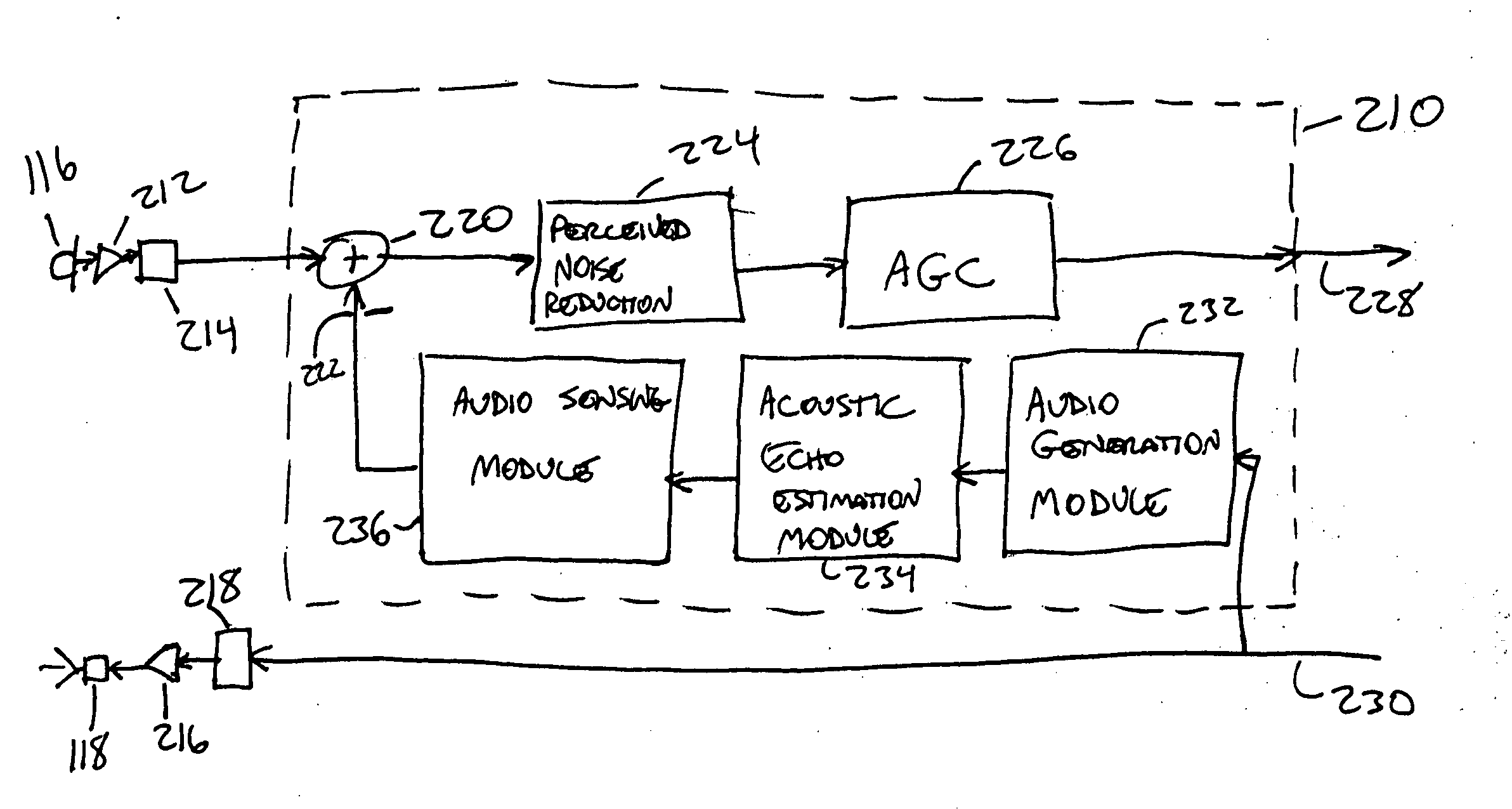
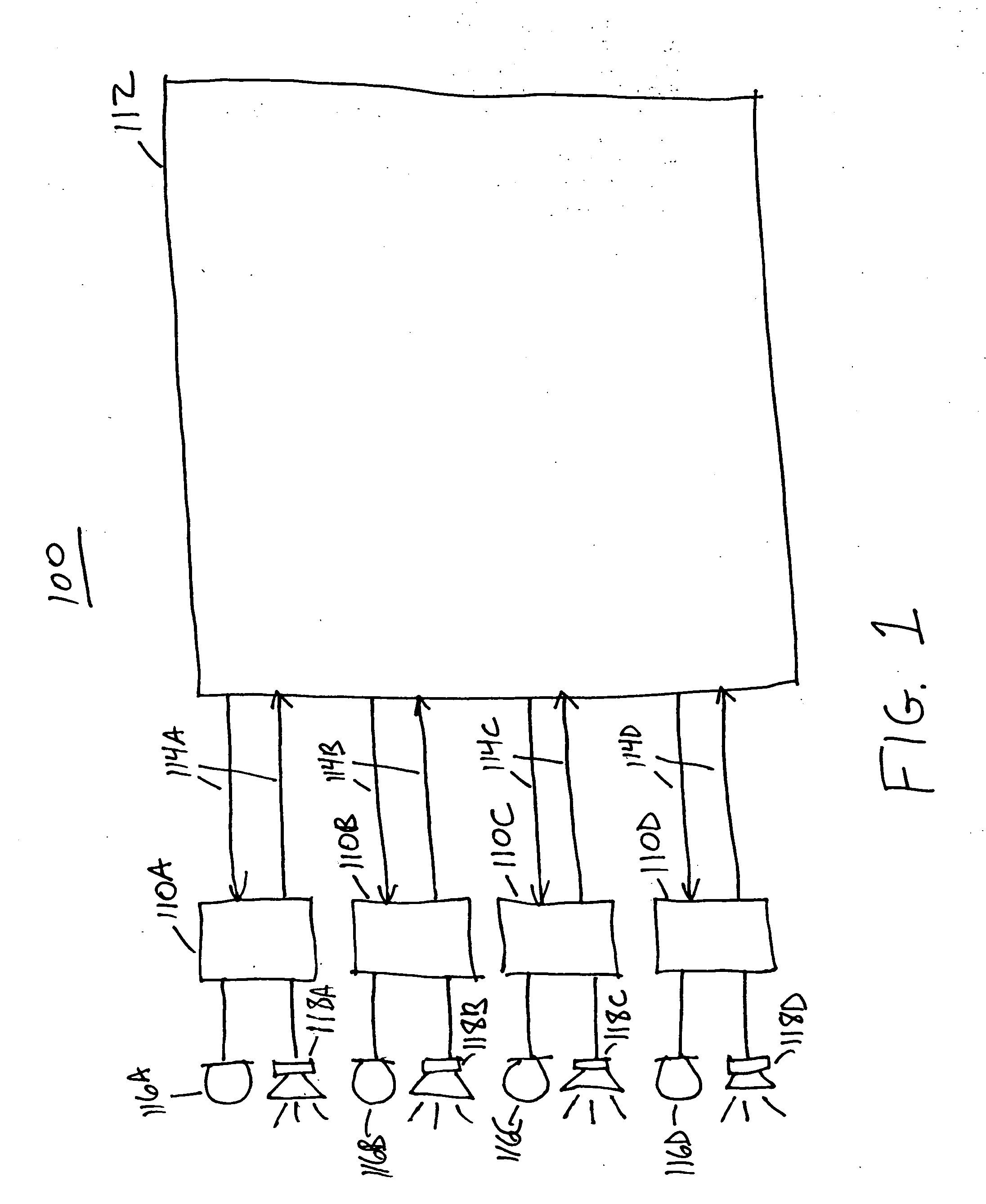
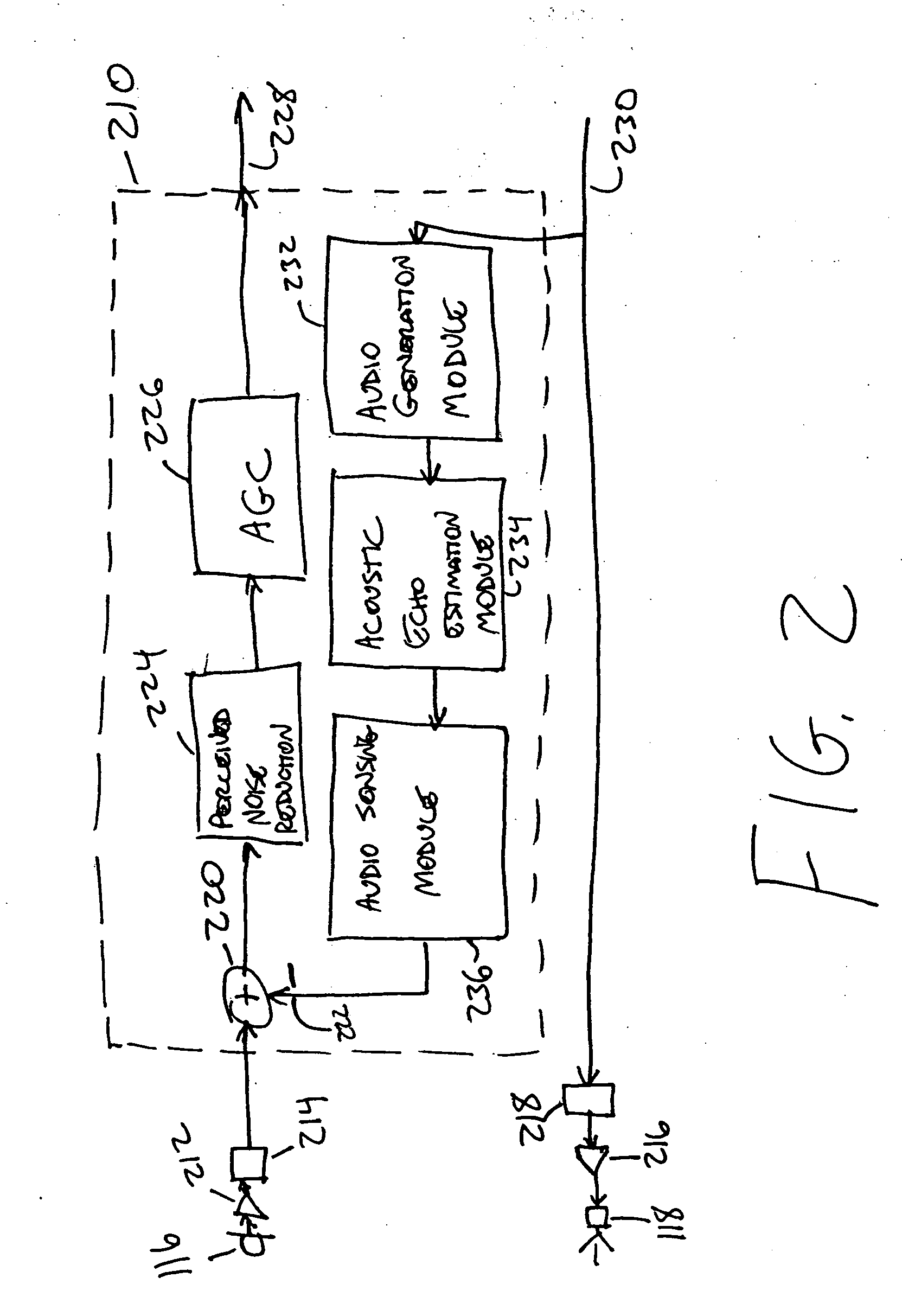
[0023]FIG. 1 is a high-level block diagram of an audio communications system 100 according to an embodiment of the present invention. A plurality of terminals 110A-D are coupled to a switch 112 via communications links 114A-D. The terminal types can be heterogeneous or homogeneous. In one embodiment, the terminals include: dedicated speakerphones, desktop handsets with or without speakerphone capabilities, cellular phones, and / or personal computer (PC) systems with audio capabilities. As used herein, the phrase “audio communications system” also includes video conferencing systems having audio capabilities. Each terminal 110, of which terminal 110A is representative, preferably includes a microphone 116A and a loudspeaker 118A. As is known in the art, the microphone 116 converts sound pressure waves into electrical signals and the loudspeaker 118 converts electrical signals into sound pressure waves.

[0024] The communications links 114 carry audio data representative of sounds picke...


PUM


Abstract

An audio communications system has an acoustic echo cancellation (AEC) module. The AEC module receives a digital signal sent to a loudspeaker and a digital signal received from a microphone. The signal received from the microphone contains an echo of the signal played through the loudspeaker. The loudspeaker signal is processed by an audio generation module (AGM) that models substantially nonlinear distortions that can occur while producing the signal played through the loudspeaker. The AGM includes a modeling path comprised of one or more distortion modules. Each distortion module receives digital samples as input, modifies the samples to model a form of distortion, and outputs the modified samples. The output of the AGM is provided to an acoustic echo estimation (AEE) module that uses adaptive algorithms to compensate for substantially linear changes in the echo characteristics of the environment in which the loudspeaker and microphone are located.

Description

CROSS-REFERENCE TO RELATED APPLICATION [0001] This application is a continuation of U.S. Ser. No. 09 / 699,188, filed on Oct. 27, 2000, entitled DISTORTION COMPENSATION IN AN ACOUSTIC ECHO CANCELER, by inventor James H. Parry, currently pending [Attorney Docket No. 38715-P014US].BACKGROUND OF THE INVENTION [0002] 1. Field of Invention [0003] This invention pertains in general to telephony and televideo conferencing and in particular to performing acoustic echo cancellation on potentially distorted audio signals. [0004] 2. Background of Invention [0005] Two-way audio communications systems, such as speakerphones and video communications systems having audio capabilities, utilize both a microphone and a loudspeaker. The microphone transmits speech and other sounds from the local terminal to remote terminals while the loudspeaker emits sounds received from remote terminals. In a typical hands-free system, the loudspeaker and microphone are located in close proximity and sounds produced b...

Claims


Application Information

Patent Timeline
Patent Type & Authority Applications(United States)
IPC IPC(8): H04M9/08
CPCH04M9/082
Inventor PARRY, JAMES H.
Owner CISCO TECH INC
Why Eureka
Try Eureka