Apparatus and method for scanning an object

a three-dimensional shape and object technology, applied in the field of objects scanning, can solve the problems of only two measurements of the foot, poor fitting shoes can affect the hitting performance of golfers, and golfers often experience blisters caused, etc., and achieve the effect of small apertur

Inactive Publication Date: 2006-02-16
ACUSHNET CO
View PDF24 Cites 26 Cited by
  • Summary
  • Abstract
  • Description
  • Claims
  • Application Information

AI Technical Summary

Benefits of technology

[0008] The present invention is directed a scanner having a plurality of cameras positioned around an object to be scanned, and the object, covered by a textured surface, is illuminated by unstructured light. Preferably, at least two cameras are arranged in pairs and are located proximate to each other, and the cameras in the pairs are positioned offset to each other in two directions, e.g., horizontal and vertical. Offsetting camera pairs provide a depth perception of the scanned object. At least three camera pairs are used to scan a foot, and two pairs can be used with a foot stop. The camera pairs are positioned such that at least two camera pairs' fields of vision overlap each other. The cameras should have small aperture so that the lenses do not need to be focused within a distance away from the cameras.

Problems solved by technology

Golfers often experience blistering caused by poorly fitting golf shoes.
Poorly fitting shoes can also affect the golfers' hitting performance by not providing a stable base for their feet during golf swings.
One problem associated with the Brannock device is that its foot measurements are only two dimensional in nature, measuring an absolute length from heel to toe and the width.
This method fails to take into consideration factors such as type of heel, e.g., bony versus padded; shape of the toes, e.g., square versus tapered; insole arch; and other characteristics.
This device also fails to measure characteristics associated with medical problems such as bunions, which require larger shoe sizes to accommodate abnormalities of the foot.
Since all areas of the foot are important for a proper fit, omitting these areas is undesirable.
This method of illumination takes time and requires a control mechanism for the laser.
Furthermore, laser systems are expensive.
The foot needs to remain stationary for a relatively long time for the camera to image all sides of the foot.

Method used


Image

  • Apparatus and method for scanning an object
  • Apparatus and method for scanning an object
  • Apparatus and method for scanning an object

Examples


Embodiment Construction

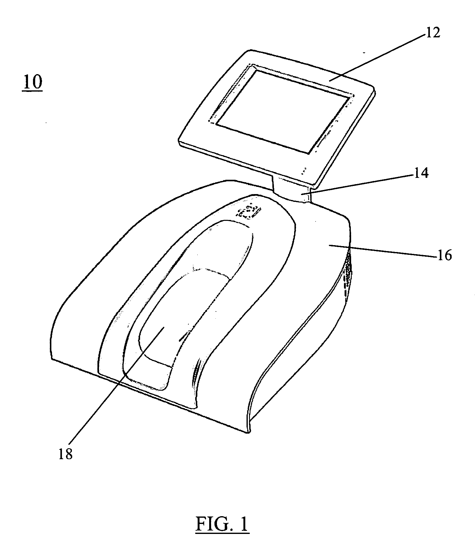
[0026] Referring to FIG. 1, scanner 10 comprises a display or monitor 12 supported by neck 14 on housing 16. Display 12 preferably has touch screen capability to interact with users. Neck 14 can be telescopic so that monitor 12 can be raised or lowered. Housing 16 defines cavity 18, which is sized and configured to receive an object to be scanned. Any three-dimensional object can be scanned, and cavity 18 can be enlarged to accommodate objects of any size. The present invention is described below using a foot; however, the present invention is not limited to any particular scanned object.

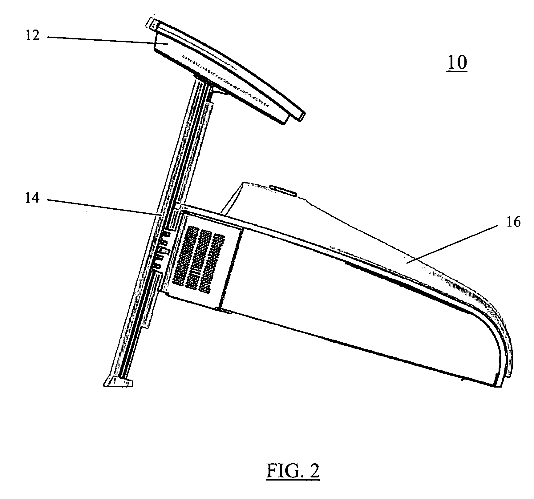
[0027] As shown in FIG. 2, housing 16 is preferably orientated at an incline relative to a surface supporting the scanner. The inventors of the present invention have determined that a foot inclined at a predetermined range of inclination angles exerts even pressure on the foot. In other words, at the preferred inclination the foot exerts even pressure on the heel and the balls. Advantageously, no ...


PUM


Abstract

A scanner has a plurality of cameras positioned around an object to be scanned. The object is illuminated by unstructured light and the object is covered by a textured surface. The cameras can be arranged as pairs and each camera pair is supported on a single support. The scanned object can be a foot, among other things, and the scanner is positioned at a predetermined incline so that the foot is evenly supported. Method for attaching the camera pairs on the support, method for calibrating the camera pairs and method of scanning the foot to provide shoe sizes and shoe lasts are also disclosed.

Description

FIELD OF THE INVENTION [0001] This invention relates generally to an apparatus and method for scanning an object. More particularly, this invention relates to an apparatus and method for scanning the three-dimensional shape of a foot. BACKGROUND OF THE INVENTION [0002] The footwear industry has become a large, specialized, and competitive environment. The industry has long-established methods of operation, one of which is to determine shoe size based upon the length and width of the foot. Shoe lasts, which are solid forms upon which shoes are constructed, for each shoe size are used in the manufacture of shoes. Therefore, properly sized lasts are essential for a successful shoe line. Properly fitting shoes are always important to consumers, but fit can be particularly important for golfers, who wear relatively stiff golf shoes over varied terrain, for relatively long periods of time, and in varied weather conditions. Golfers often experience blistering caused by poorly fitting golf ...

Claims


Application Information

Patent Timeline
Patent Type & Authority Applications(United States)
IPC IPC(8): G06K9/20A43D1/02G01B11/24
CPCG01B11/24A43D1/025
Inventor PISHDADIAN, HAMIDGENGA, RICHARD A. JR.SCHINAZI, ALANSIROTIN, JUSTIN W.
Owner ACUSHNET CO
Why Eureka
Try Eureka