Abrasivejet cutting head with back-flow prevention valve

a technology of backflow prevention valve and cutting head, which is applied in the field of abrasivejet systems, can solve the problems of affecting production schedules, increasing production costs, and abrasive-laden water backing up to and into external hoppers

Inactive Publication Date: 2006-02-16
INT WATERJET PARTS INC AN IDAHO CORP
View PDF9 Cites 39 Cited by
  • Summary
  • Abstract
  • Description
  • Claims
  • Application Information

AI Technical Summary

Problems solved by technology

During operation of abrasivejet systems, the fluid path between the mixing region and the discharge opening of the abrasivejet nozzle can become clogged or blocked sufficiently to cause the abrasive-laden wat...

Method used


Image

  • Abrasivejet cutting head with back-flow prevention valve
  • Abrasivejet cutting head with back-flow prevention valve
  • Abrasivejet cutting head with back-flow prevention valve

Examples


Embodiment Construction

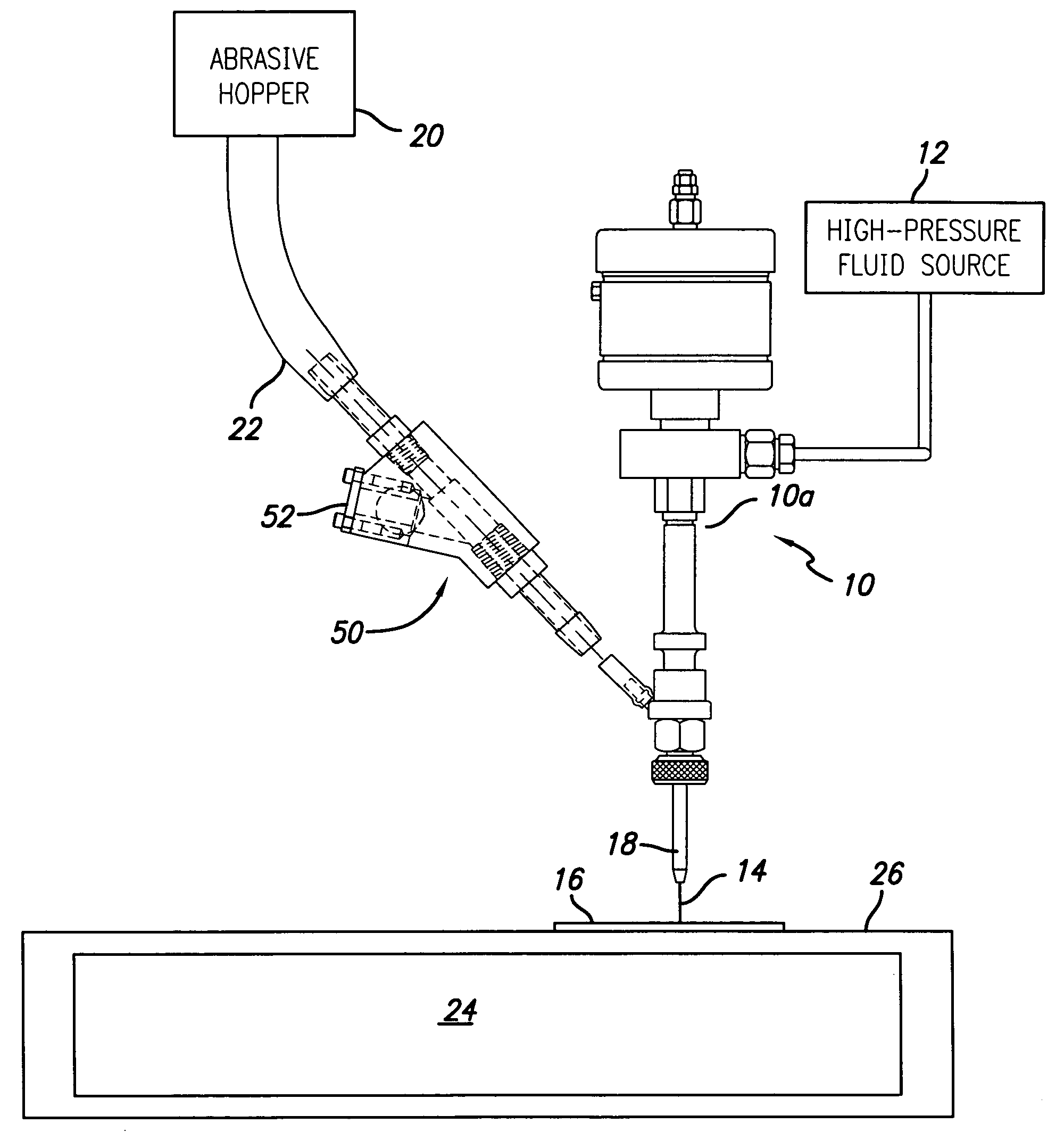
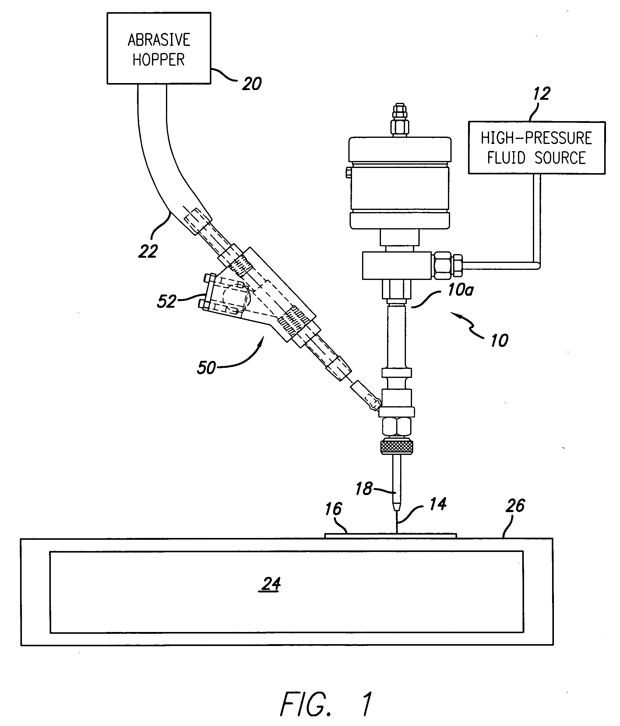
[0013] Referring now to the FIG. 1 wherein depicted elements are not necessarily shown to scale and wherein like or similar elements will be designated by the same reference numerals through the several views, FIG. 1 is a schematic illustration of an abrasivejet cutting system constructed in accordance with the invention. A cutting head 10 is coupled at its upstream end 10a to a source 12 of high pressure fluid such as water. As known by those skilled in the art, the cutting head includes an orifice member (not illustrated) in its upstream region that has a waterjet-forming orifice formed in a hard jewel material such as ruby, sapphire or the like. The highly pressurized fluid is forced through the orifice, resulting in the formation of a highly cohesive waterjet that can reach speeds in excess of the speed of sound.

[0014] To increase the cutting power of the waterjet, it is known in the art to entrain abrasive into the jet to form an abrasivejet. Abrasive, such as garnet or silica...


PUM

PropertyMeasurementUnit
Angleaaaaaaaaaa
Angleaaaaaaaaaa
Pressureaaaaaaaaaa

Abstract

An abrasivejet cutting head is disclosed that includes a valve assembly for presenting back-flow to the abrasive hopper of abrasive-laden fluid from the cutting head when the discharge path for the abrasivejet becomes clogged or otherwise blocked. The valve assembly is positioned within the abrasive line to conduct abrasive from the hopper towards the abrasivejet nozzle. The valve assembly further includes a discharge path which is scaled off from the abrasive jet nozzle during normal operation in response to the relative lower pressure in the abrasivejet nozzle that results from the flowing fluid therein. If the jet path is blocked or impeded in a manner that causes a backflow of the abrasive-laden slurry therein, the cessation of low-pressure permits the backflowing slurry to exit via the discharge path and bypass the hopper, substantially avoiding the downtime previously required to clean the hopper.

Description

TECHNICAL FIELD [0001] This invention relates to abrasivejet systems. BACKGROUND OF THE INVENTION [0002] The use of high velocity, abrasive-laden liquid jets to precisely cut a variety of materials is well known. Briefly, a high velocity liquid jet is first formed by compressing the liquid to an operating pressure of 3,500 to 150,000 psi, and forcing the compressed liquid through an orifice having a diameter approximating that of a human hair; namely, 0.003-0.040 inches. The material defining the waterjet-forming orifice is typically a hard jewel such sapphire, ruby or diamond. [0003] The resulting highly coherent jet is discharged from the orifice at a velocity which approaches or exceeds the speed of sound. The liquid most frequently used to from the jet is water, and the high velocity jet described hereinafter may accordingly be identified as a waterjet. Those skilled in the art will recognize, however, that numerous other liquids can be used without departing from the scope of t...

Claims


Application Information

Patent Timeline
IPC IPC(8): B24C7/00
CPCB24C1/045B24C7/0076B24C7/0069B24C7/0061
Inventor CHISUM, DENNISSWENSON, STANLEY
Owner INT WATERJET PARTS INC AN IDAHO CORP
Why Eureka
Try Eureka