Providing hardware independence to automate code generation of processing device firmware

Active Publication Date: 2006-02-16
MONTEREY RES LLC
View PDF69 Cites 19 Cited by
  • Summary
  • Abstract
  • Description
  • Claims
  • Application Information

AI Technical Summary

Problems solved by technology

Design changes during this conventional approach may result in costly and inefficient code changes, may cause software and hardware architecture changes

Method used


Image

  • Providing hardware independence to automate code generation of processing device firmware
  • Providing hardware independence to automate code generation of processing device firmware
  • Providing hardware independence to automate code generation of processing device firmware

Examples


Embodiment Construction

[0018] In the following description, numerous specific details are set forth to provide a thorough understanding of embodiments of the invention. One skilled in the relevant art will recognize, however, that embodiments of the invention can be practiced without one or more of the specific details, or with other methods, components, materials, etc. In other instances, well-known structures, materials, or operations are not shown or described in detail to avoid obscuring understanding of this description.

[0019] Reference throughout this specification to “one embodiment” or “an embodiment” means that a particular feature, structure, or characteristic described in connection with the embodiment is included in at least one embodiment of the present invention. Thus, the appearances of the phrases “in one embodiment” or “in an embodiment” in various places throughout this specification are not necessarily all referring to the same embodiment. Furthermore, the particular features, structur...


PUM


Abstract

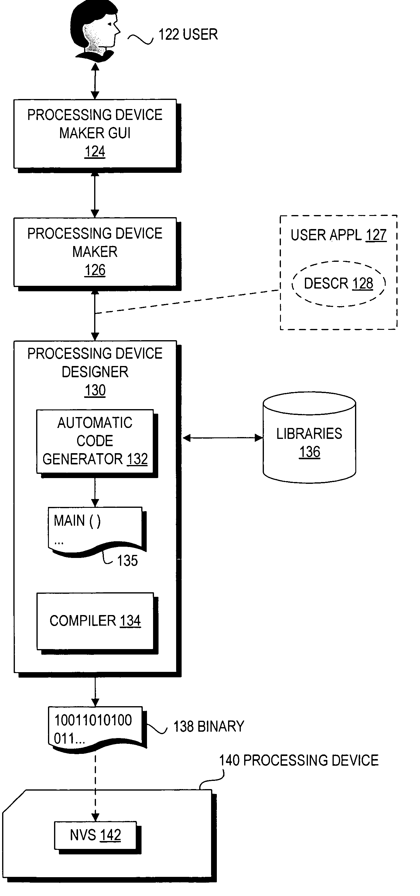
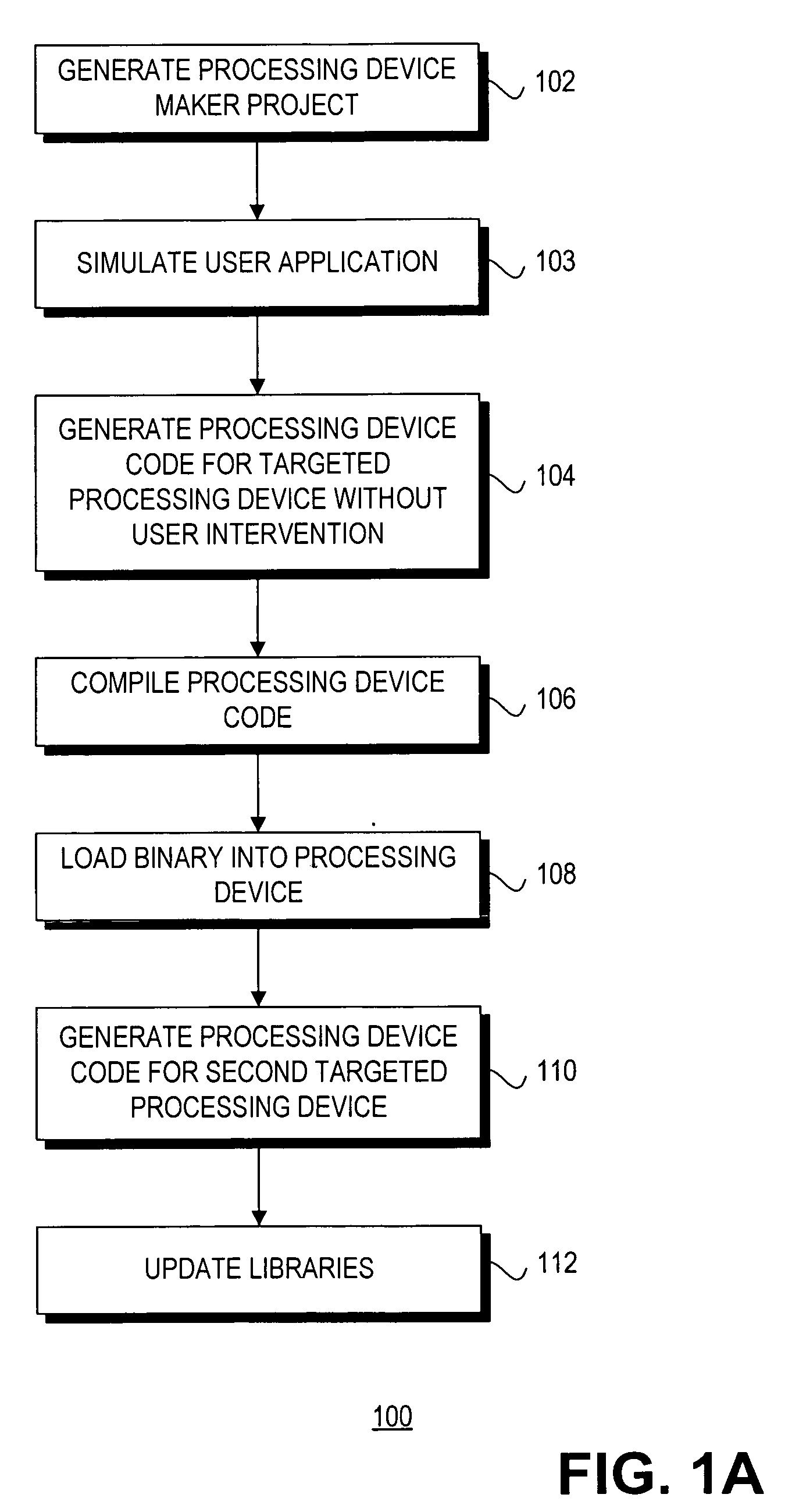
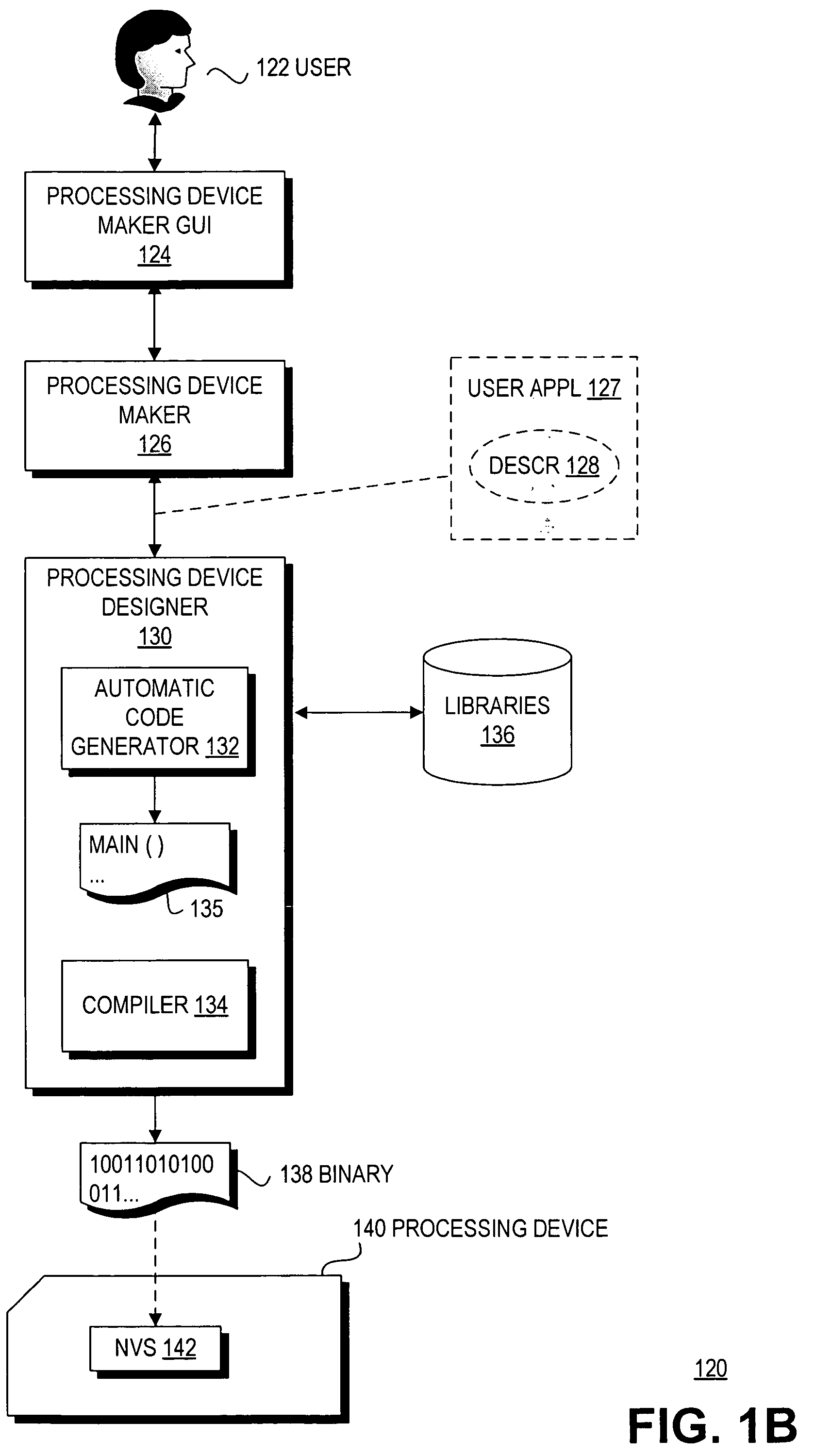
A user application is generated in response to user input, wherein the user application is described in a user application description. Processing device code is generated for a targeted processing device based at least in part on the user application description without user intervention, wherein the processing device code includes a system layer, wherein functionality of the system layer is independent of the targeted processing device.

Description

CROSS-REFERENCE TO RELATED APPLICATIONS [0001] This application claims the benefit of U.S. Provisional Application No. 60 / 601,225, filed Aug. 13, 2004, and incorporated herein by reference in its entirety.BACKGROUND [0002] 1. Field [0003] Embodiments of the invention relate to the field of processing devices and more specifically, but not exclusively, to providing hardware independence to automate generation of processing device firmware. [0004] 2. Background Information [0005] Processing devices, such as microcontrollers, are widely used in the industry as control elements in many solutions. Most microcontrollers are general in purpose, and are designed for use in a wide variety of problem solutions. As microcontrollers become more programmable and more widely applicable, a designer needs more specific device knowledge to use the microcontroller to solve a problem. [0006] In a conventional solution, hardware and software are usually created for a specific microcontroller, and may b...

Claims


Application Information

Patent Timeline
IPC IPC(8): G06F9/45
CPCG06F8/65G06F8/30
Inventor SNYDER, WARRENMAHESHWARI, DINESHOGAMI, KENNETHHASTINGS, MARK
Owner MONTEREY RES LLC
Why Eureka
Try Eureka