Self-propelling cleaner

a self-propelling, cleaner technology, applied in the direction of vacuum cleaners, cleaning equipment, domestic applications, etc., can solve the problems of large dust stuck, inconvenient cleaning, and inability to clean, so as to achieve the effect of facilitating the cleaning of self-propelling cleaners

Inactive Publication Date: 2006-02-23
FUNAI ELECTRIC CO LTD
View PDF6 Cites 186 Cited by
  • Summary
  • Abstract
  • Description
  • Claims
  • Application Information

AI Technical Summary

Benefits of technology

[0006] One of objects of the present invention is to provide a self-propelling cleaner that prevents an event that cleaning is performed in a state that a large amount of dust is stuck to the rotary brush by thoroughly removing dust from the rotary brush with prescribed timing, and to thereby allow a user to manipulate the self-propelling cleaner with greater ease.

Problems solved by technology

However, conventional vacuum cleaners are not equipped with any structure for removing dust that is stuck to the rotary brush and users are required to manually remove dust that is stuck to the rotary brush.
Therefore, cleaning is not performed in a state that a large amount of dust is stuck to the rotary brush.
As a result, the self-propelling cleaner continues to move while dropping dust from the rotary brush, to cause a situation that the room is scattered with pieces of dust that have fallen off the rotary brush, that is, the room is not cleaned.
However, there is a problem that this is a heavy work load to the user.

Method used


Image

  • Self-propelling cleaner
  • Self-propelling cleaner
  • Self-propelling cleaner

Examples


Embodiment Construction

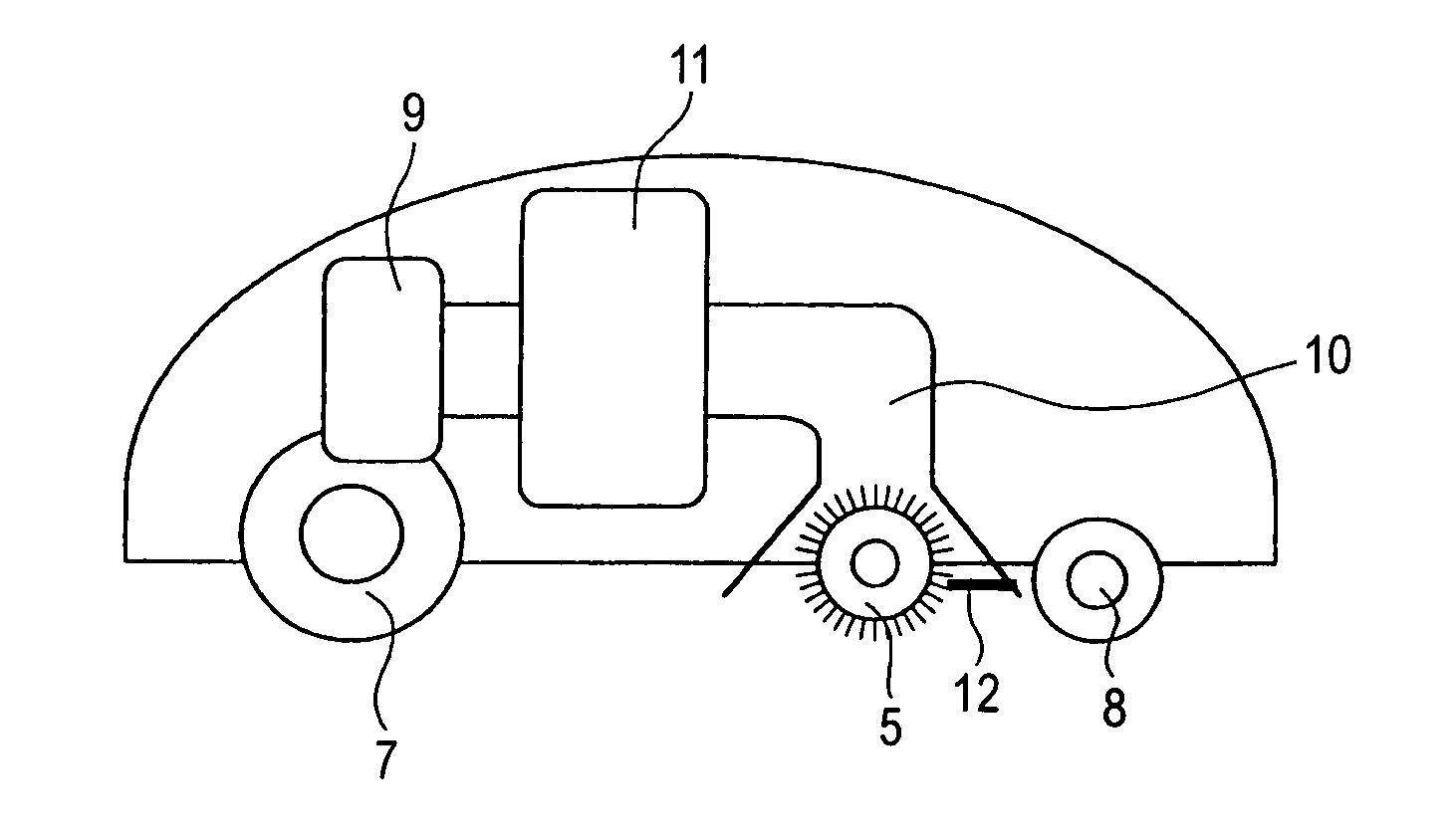
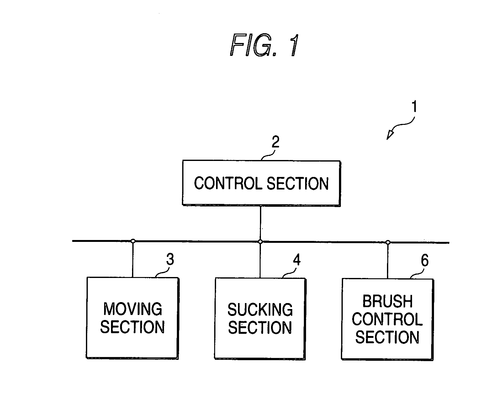
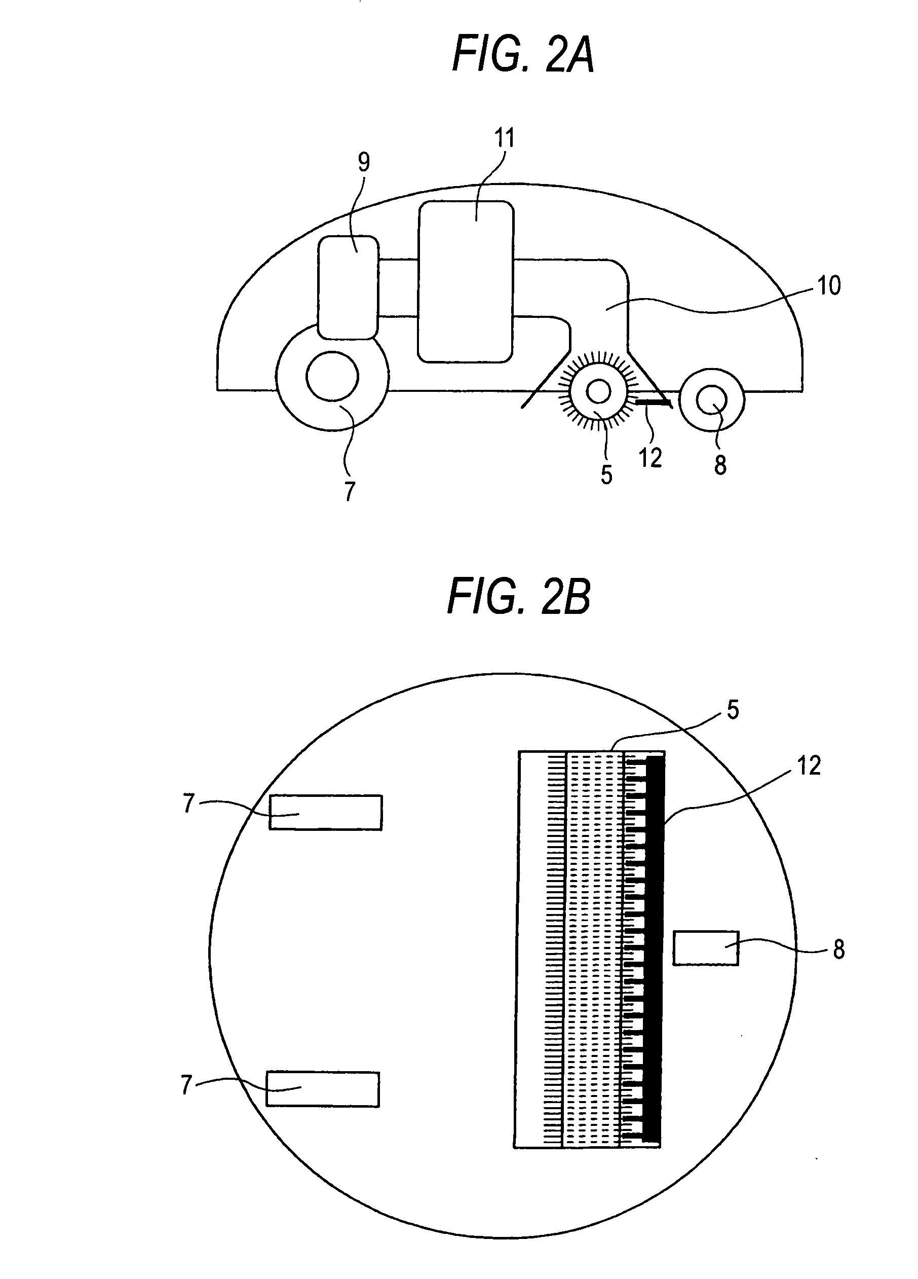
[0015]FIG. 1 is a block diagram showing the configuration of a self-propelling cleaner according to an embodiment of the present invention. FIGS. 2A and 2B are schematic diagrams of the self-propelling cleaner 1 according to the embodiment of the invention; wherein FIG. 2A is a side sectional view and FIG. 2B is a bottom view. The self-propelling cleaner 1 includes a control section 2 for controlling operation of the main body, a moving section 3 for controlling the rotation speeds of tires individually, a sucking section 4 for sucking dust into the main body through a suction mouth that is provided in the main body by rotating a suction fan, and a brush control section (dust removing section) 6 for kicking up dust on a floor or removing dust from a rotary brush 5 that is attached to the suction mouth by controlling the rotation direction of the rotary brush 5. The control section 2 stores a map that contains information indicating along what route the self-propelling cleaner should...


PUM


Abstract

A self-propelling cleaner 1 performs dust removal processing in which a comb is brought close to a rotary brush with prescribed timing and dust is removed from the rotary brush. In the dust removal processing, the comb is slid in such a direction as to come closer to the brush, even dust that is stuck to the base portions of bristles of the rotary brush can be removed. A self-propelling cleaner is provided that is free of an event that it performs cleaning in a state that a large amount of dust is stuck to the rotary brush.

Description

BACKGROUND OF THE INVENTION [0001] 1. Field of the Invention [0002] The present invention relates to a self-propelling cleaner that cleans a cleaning area while moving therein automatically. [0003] 2. Description of the Related Art [0004] Among conventional vacuum cleaners are ones in which a suction mouth is provided with a rotary brush for kicking up dust on the floor and dust kicked up by the rotary brush is sucked through the suction mouth. Since the rotary brush kicks up dust on the floor, dust tends to stick to its surfaces. In view of this, JP-A-11-137488 proposes a technique for decreasing the amount of dust that is stuck to the rotary brush. In the technique proposed in JP-A-11-137488, air intake portions are provided at both ends of the rotary brush and its outer circumferential surface is formed with blowholes. A sucked air flow that has been introduced into the rotary brush through the air intake portions flows out through the blowholes. The air that flows through the bl...

Claims


Application Information

Patent Timeline
Patent Type & Authority Applications(United States)
IPC IPC(8): A47L5/00A47L7/00A47L9/00A47L9/04
CPCA47L2201/00A47L9/0477
Inventor SHIMIZU, AKITAKA
Owner FUNAI ELECTRIC CO LTD
Why Eureka
Try Eureka