Evaporative fuel supply apparatus

Inactive Publication Date: 2006-02-23
TOYOTA JIDOSHA KK
View PDF9 Cites 9 Cited by
  • Summary
  • Abstract
  • Description
  • Claims
  • Application Information

AI Technical Summary

Benefits of technology

[0013] The present invention has been made to solve the above problem. It is an object of the present inventi

Problems solved by technology

When the evaporative fuel is supplied to the intake path, the air-fuel ratio is likely to become disordered.
Under the above circumstances, however, the amount of fuel supply to the internal combustion engine is insufficient so that cylinder combustion may not properly take place during an explosion stroke.
Consequently, no provision is made in the conventi

Method used


Image

  • Evaporative fuel supply apparatus
  • Evaporative fuel supply apparatus
  • Evaporative fuel supply apparatus

Examples


first embodiment

Operation Specific to First Embodiment

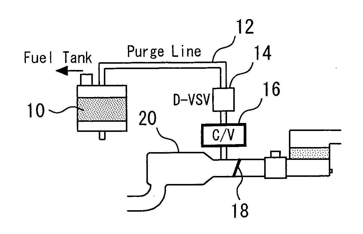
[0057] The apparatus according to the present embodiment permits evaporative fuel, which is generated in the fuel tank during an internal combustion engine operation or supplied from the fuel tank during fueling, to be stored in the canister 10. Further, when the internal combustion engine is to be cold-started, the apparatus can properly open the D-VSV 14 to supply the evaporative fuel in the canister 10 to the intake path 20, thereby obtaining a desired air-fuel ratio.

[0058] The opening of the D-VSV 14 is controlled by a known method so that the rate of evaporative fuel flow into the intake path 20 provides a desired air-fuel ratio. When such a control method is used, the fuel required for an internal combustion engine operation can be supplied to each cylinder in vapor form at the time of internal combustion engine cold startup.

[0059] If the internal combustion engine is cold-started, liquid fuel is not likely to vaporize. Therefore, when e...

second embodiment

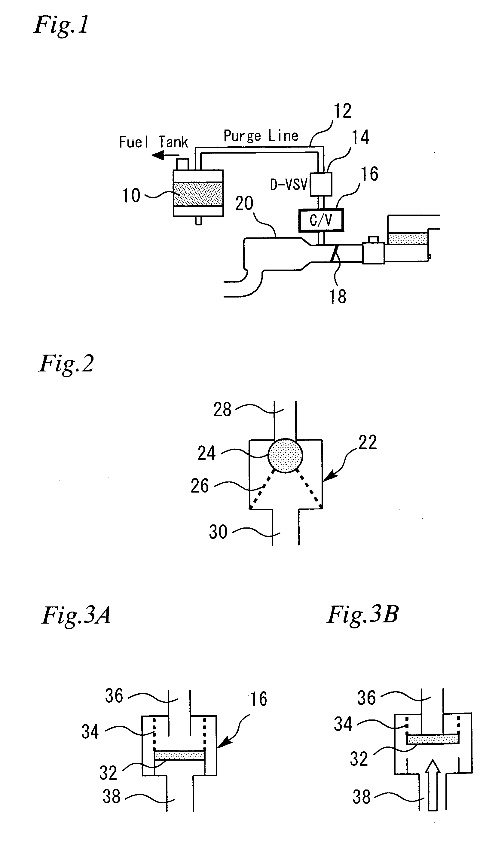
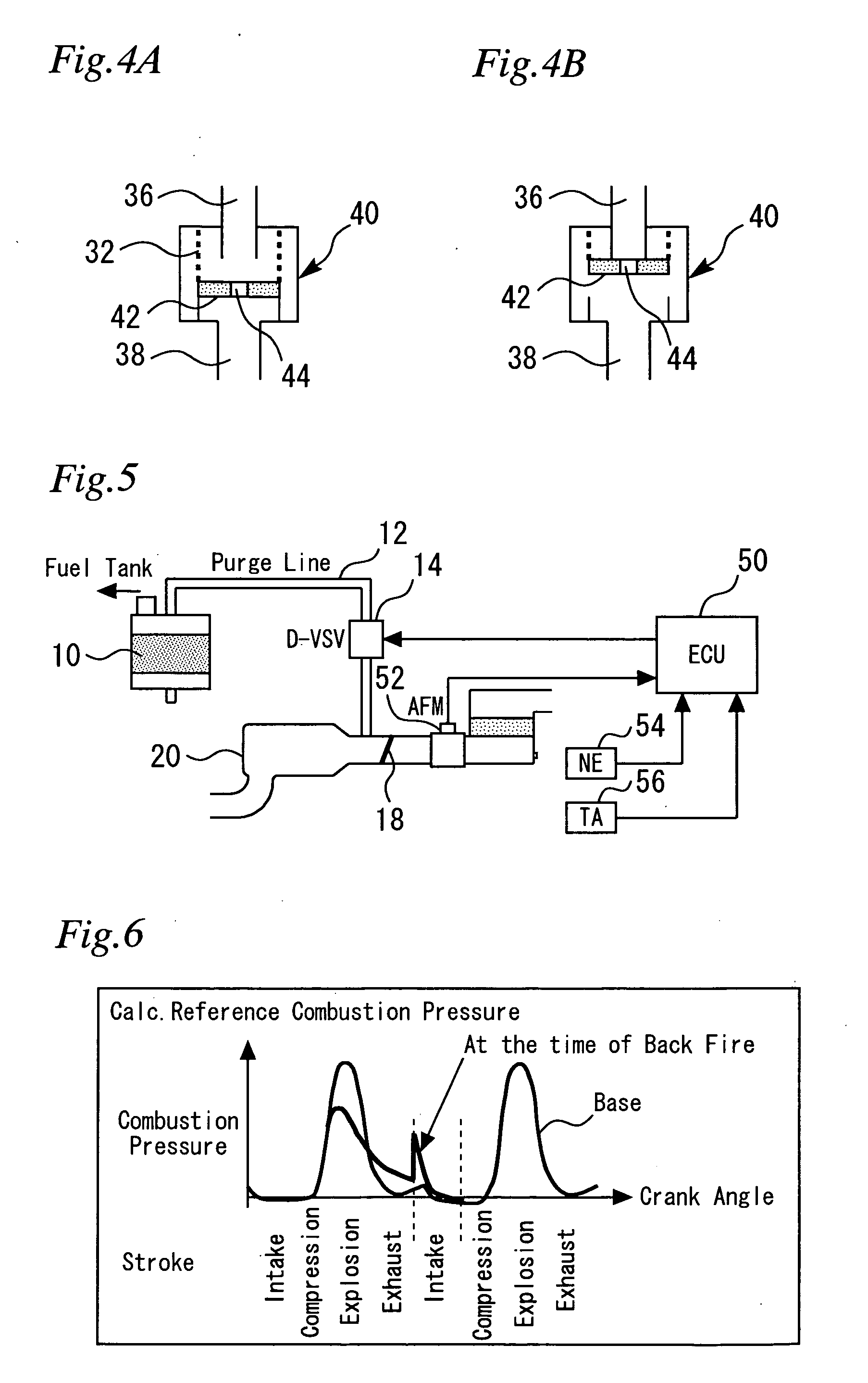
[0068] A second embodiment of the present invention will now be described with reference to FIGS. 4A and 4B. FIGS. 4A and 4B illustrate the configuration and operation of a check valve 40 for use in the present embodiment. The apparatus according to the present embodiment is the same as the apparatus according to the first embodiment except that check valve 40 is used instead of check valve 16.

[0069]FIG. 4A illustrates a normal state of the check valve 40. FIG. 4B illustrates a state of the check valve 40 that prevails when a reverse pressure is exerted. When the present embodiment is described with reference to FIGS. 4A and 4B, elements identical with those described with reference to FIGS. 3A and 3B are designated by the same reference numerals as their counterparts and omitted from the description.

[0070] As indicated in FIGS. 4A and 4B, the check valve 40 includes a valve disc 42. The valve disc 42 is provided with an orifice 44. The orifice 44 ensures that the space toward the...

third embodiment

Configuration of third embodiment

[0072] A third embodiment of the present invention will now be described with references to FIGS. 5 to 8.

[0073]FIG. 5 illustrates the configuration of an evaporative fuel supply apparatus according to the third embodiment of the present invention. When the present embodiment is described with reference to FIG. 5, elements identical with those described with reference to FIG. 1 are designated by the same reference numerals as their counterparts and omitted from the description or briefly described.

[0074] In the apparatus according to the present embodiment, the D-VSV 14 directly communicates with the intake path 20 without via the check valve 16. Further, the apparatus according to the present embodiment includes an ECU (Electronic Control Unit) 50. The ECU 50 is connected to the D-VSV 14 and an air flow meter 52. The air flow meter 52 is a sensor that is positioned upstream of the throttle valve 18 to detect an intake air amount GA of the internal...


PUM


Abstract

A canister is furnished to store evaporative fuel. A purge line is furnished to ensure that the canister communicates with an internal combustion engine intake path. The purge line is provided with a D-VSV (purge control valve) that controls the continuity of the purge line. Further, a check valve is furnished to control the pressure propagation from the intake path to the canister at the time of backfiring.

Description

BACKGROUND OF THE INVENTION [0001] 1. Field of the Invention [0002] The present invention relates to an evaporative fuel supply apparatus, and more particularly to an evaporative fuel supply apparatus that is suitable for supplying evaporative fuel to an internal combustion engine intake system when an internal combustion engine is to be cold-started. [0003] 2. Background Art [0004] A conventionally known system disclosed, for instance, by Japanese Patent Laid-Open No. Hei7-229452 stores evaporative fuel, which is generated within a fuel tank, in a canister, and supplies the stored fuel to an intake path during an internal combustion engine operation. When the evaporative fuel is supplied to the intake path, the air-fuel ratio is likely to become disordered. Therefore, the evaporative fuel is generally supplied after internal combustion engine warm-up. [0005] When the temperature is low, liquid fuel is not likely to vaporize. Therefore, the supply of already evaporative fuel to the ...

Claims


Application Information

Patent Timeline
IPC IPC(8): F02M25/08
CPCF02D13/0234F02M25/089F02D41/0032F02D13/0261
Inventor OSANAI, AKINORI
Owner TOYOTA JIDOSHA KK
Why Eureka
Try Eureka