AI technical title is built by Patsnap AI team. It summarizes the technical point description of the patent document.
a technology of hand tools and power tools, applied in the field of hand tools, can solve the problems of hand tools, portable and thus easily stolen from job sites or storage areas, and existing hand tools suffer from a number of deficiencies
Inactive Publication Date: 2006-02-23
GASS STEPHEN F +1
View PDF60 Cites 73 Cited by
Summary
Abstract
Description
Claims
Application Information
AI Technical Summary
This helps you quickly interpret patents by identifying the three key elements:
Problems solved by technology
Method used
Benefits of technology
Problems solved by technology
Existing hand tools suffer from a number of deficiencies.
For instance, hand tools, by their very nature are portable and thus easily stolen from job sites or storage areas.
With battery powered tools, the weight of the tool is often excessive for comfortable extended use.
Conventional electrically powered tools also do not allow the user to optimize the tool for use with the particular user's preferences, or with the specific requirements of a particular project or operating condition.
For example, many tools are not adequately flexible in their operation to accommodate particular tasks easily and conveniently.
By way of example, drill / drivers are used to drill holes and drive screws, however, existing designs do not always accomplish these functions in the most efficient or reliable matter.
When driving screws, for instance, it is often difficult to accurately control the depth of the screw with existing drills.
Similarly, existing drills do not provide sufficient control of torque, speed and / or number of revolutions.
In some applications, the physical configuration of the drill is not well suited to allow access to the work sites.
Method used
Image
Click on the blue label to locate the original text in one second.
Reading with bidirectional positioning of images and text.
Examples
Embodiment Construction
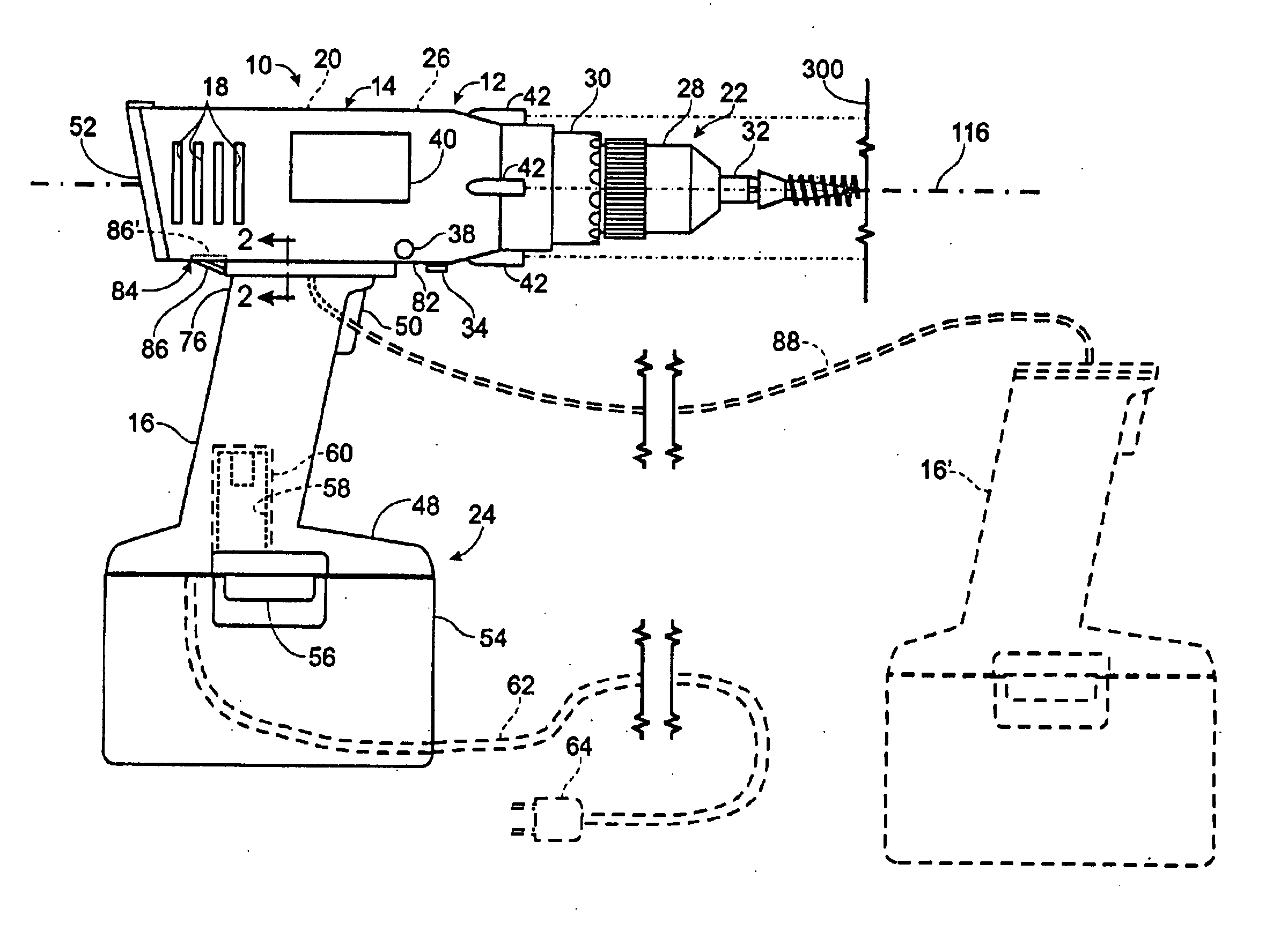
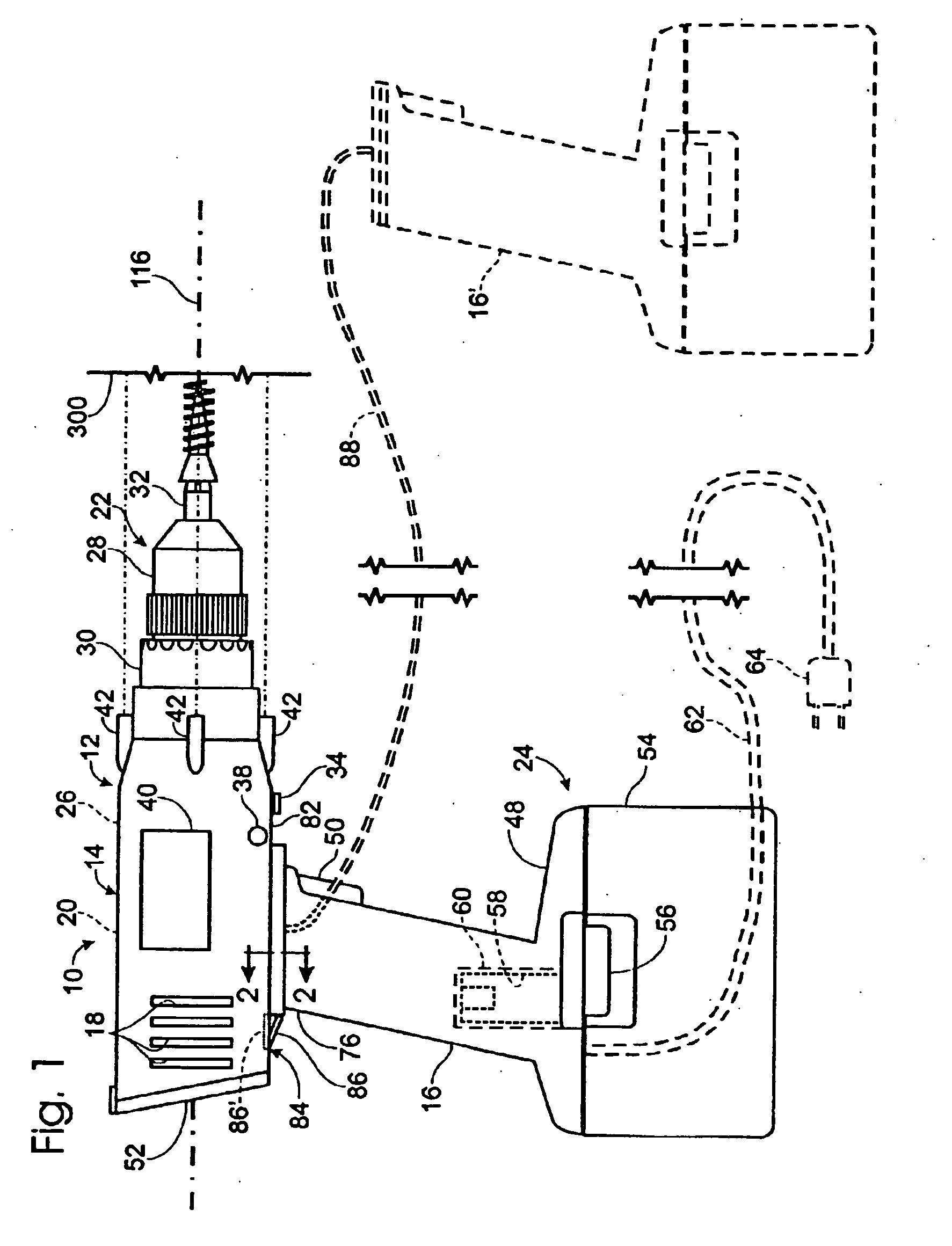
[0042] An electrically powered hand tool constructed according to the present invention is shown in FIG. 1 and generally indicated at 10. Tool 10 includes a body 12 with a housing 14, a handle 16 and a plurality of vents 18 for providing ventilation and cooling to a motor 20, which is contained within the housing. Tool 10 further includes a work element 22 in the form of a keyless chuck 28, a power source 24, a controller 26 and a manual clutch, or torque control, 30. Work element 22 is adapted to receive a bit, such as the screwdriver bit shown in FIG. 1 at 32 and is connected to a drive-train (not shown) such as is well known in the art. Examples of suitable torque control and drive-train mechanisms are disclosed in U.S. Pat. Nos. 4,161,242, 5,440,215, 5,458,206, 5,624,000 and 5,704,433, the disclosures of which are hereby incorporated by reference.
[0043] Also shown in FIG. 1 is a reversing switch 34 that selectively reverses the direction in which the motor rotates the work elem...
PUM
Property
Measurement
Unit
distance
aaaaa
aaaaa
time
aaaaa
aaaaa
deliver power
aaaaa
aaaaa
Abstract
An electrically powered hand tool is disclosed. The tool includes a motor, a power source, a work element and a controller. Various alternative features, embodiments and operative configurations are disclosed.
Description
CROSS-REFERENCE TO RELATED APPLICATIONS [0001] This application is a divisional of U.S. patent application Ser. No. 11 / 021,641, filed Dec. 23, 2004, which is a continuation of U.S. patent application Ser. No. 10 / 385,215, filed Mar. 10, 2003, issued as U.S. Pat. No. 6,834,730 on Dec. 28, 2004, and which is a continuation of U.S. patent application Ser. No. 09 / 615,388, filed Jul. 13, 2000, issued as U.S. Pat. No. 6,536,536 on Mar. 25, 2003, which is a continuation-in-part of U.S. patent application Ser. No. 09 / 302,162, filed Apr. 29, 1999, which is based upon and claims priority from U.S. Provisional Patent Application Ser. No. 60 / 144,399, filed Jul. 16, 1999 and U.S. Provisional Patent Application Serial No. 60,149,944, filed Aug. 19, 1999. The complete disclosures of all of the above applications are hereby incorporated by reference for all purposes.FIELD OF THE INVENTION [0002] The invention relates generally to hand tools, and more particularly to electrically powered hand tools. ...
Claims
Application Information
Patent Timeline
Application Date:The date an application was filed.
Publication Date:The date a patent or application was officially published.
First Publication Date:The earliest publication date of a patent with the same application number.
Issue Date:Publication date of the patent grant document.
PCT Entry Date:The Entry date of PCT National Phase.
Estimated Expiry Date:The statutory expiry date of a patent right according to the Patent Law, and it is the longest term of protection that the patent right can achieve without the termination of the patent right due to other reasons(Term extension factor has been taken into account ).
Invalid Date:Actual expiry date is based on effective date or publication date of legal transaction data of invalid patent.
Patent Type & AuthorityApplications(United States)

