Robot

a robot and robot technology, applied in the field of robots, can solve the problems of inability to obtain position information (z component) inability to measure the position of the point p, and inability to obtain the position information of the target in its depth direction

Inactive Publication Date: 2006-02-23
PANASONIC CORP
View PDF9 Cites 43 Cited by
  • Summary
  • Abstract
  • Description
  • Claims
  • Application Information

AI Technical Summary

Benefits of technology

[0056] According to the present invention as described hereinabove, the projections unit can project the annular pattern light beam encircling the main unit portion from the upper side of the main unit portion toward the floor surface around the main unit portion, the image pickup unit can pick up the projected image of the pattern light beam projected from the projections unit from the upper side of the main unit portion, the image processing device can sense the displacement of the projected image of the pattern light beam based on the image picked up by the image pickup unit and can detect the height difference potion around the robot main unit portion which is different in height from the floor surface (e.g., obstacles, persons or uneven spots on the floor surface). Therefore, when, for example, a plurality of height difference portions are simultaneously present around the main unit portion, simultaneously projecting the pattern light beams to these height difference portions from the projections unit makes it possible to determine the presence of these height difference portions at a time.

Problems solved by technology

However, from these images, positional information (z component) of the target in its depth direction cannot be obtained.
However, in such a measuring method, unless it is known that the position of the point 1 in the left-side screen corresponds to the position of the point P3 in the right-side screen, the position of the point p cannot be measured.
However, in such a measurement method, a measurement time is limited by a rotation time of the mirror 25.
More particularly, the measurement takes long time.
In the above description, the techniques to measure and recognize the three dimensional position of an object have been described, which indicated that a reliable method for binocular corresponding point detection has not yet established for the binocular vision method as shown in FIG. 9, and this causes an issue.
Moreover, while the projection methods shown in FIG. 10 and FIG. 11 makes it possible to identify projected light spots on the image and therefore does not essentially require the corresponding point detection, these methods still have the issue that unless a light spot or pattern light is expanded over the entire surface of a target, the three dimensional information on the target cannot be obtained.
As a solution for this issue, projecting parallel pattern light or throwing cross stripes pattern light are considered, but these methods have an issue of corresponding point determination as in the case of the binocular vision method, and it is also necessary to distinguish (identify) respective pattern light beams to avoid confusion of the beams.

Method used


Image

  • Robot
  • Robot
  • Robot

Examples


Embodiment Construction

[0079] Before the description of the present invention proceeds, it is to be noted that like parts are designated by like reference numerals throughout the accompanying drawings.

[0080] Hereinbelow, the embodiments of the present invention will be described in detail with reference to the drawings.

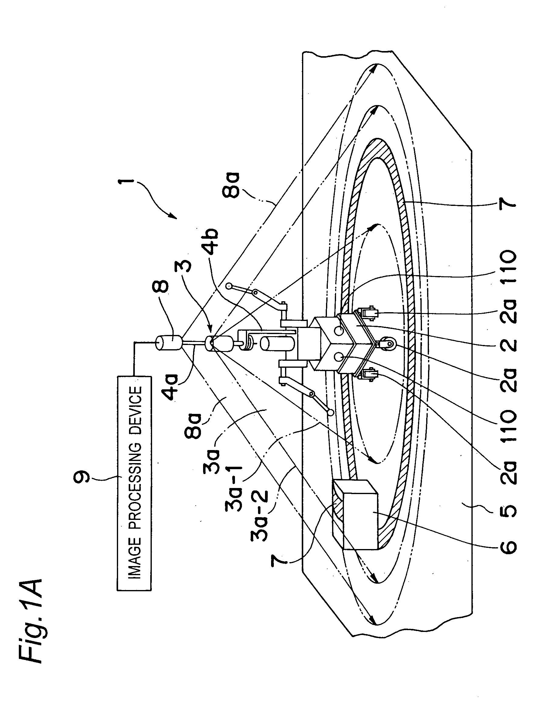
[0081] Hereinbelow, description will be given of a robot in one embodiment of the present invention with reference to FIG. 1A to FIG. 7.

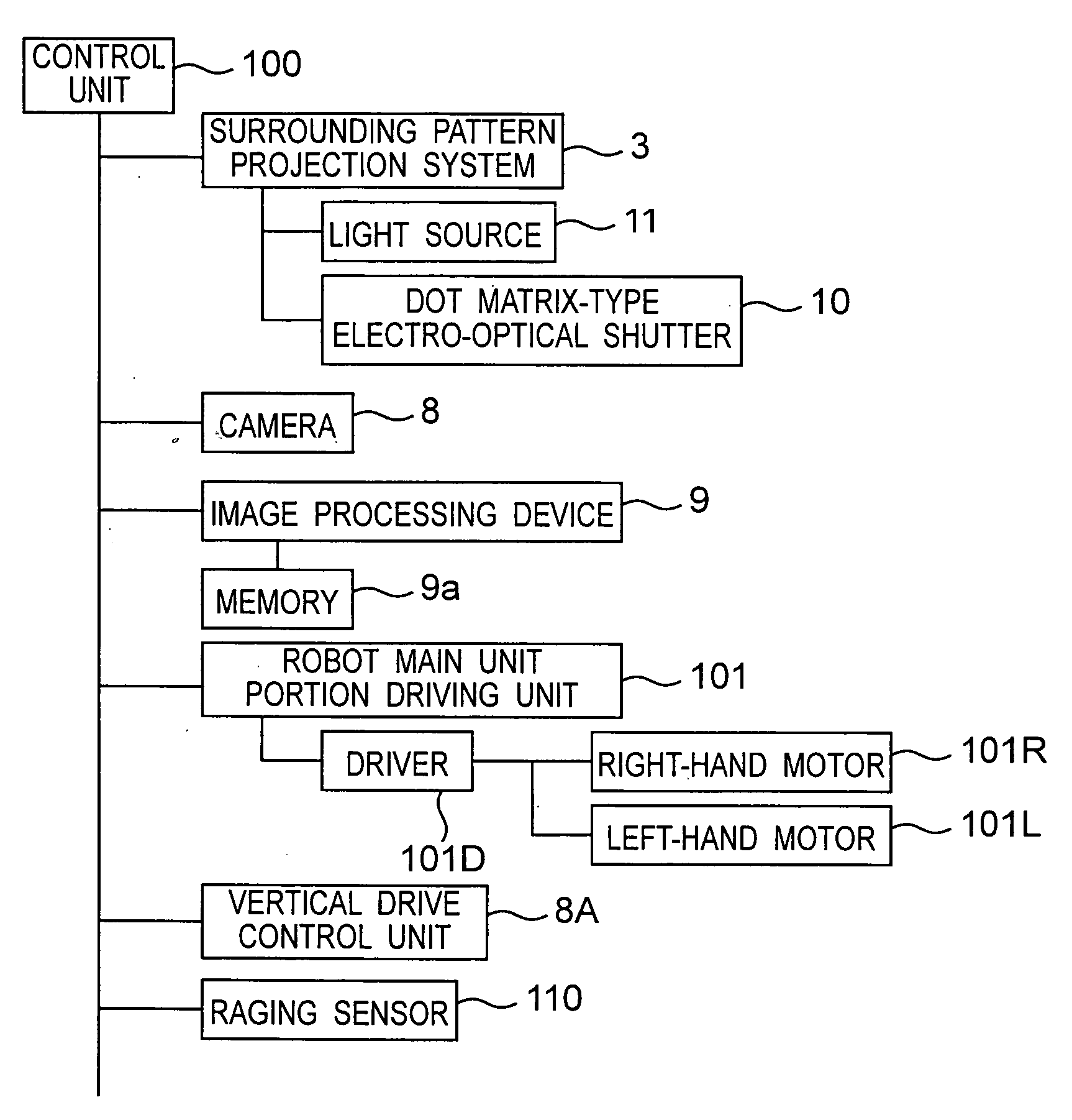
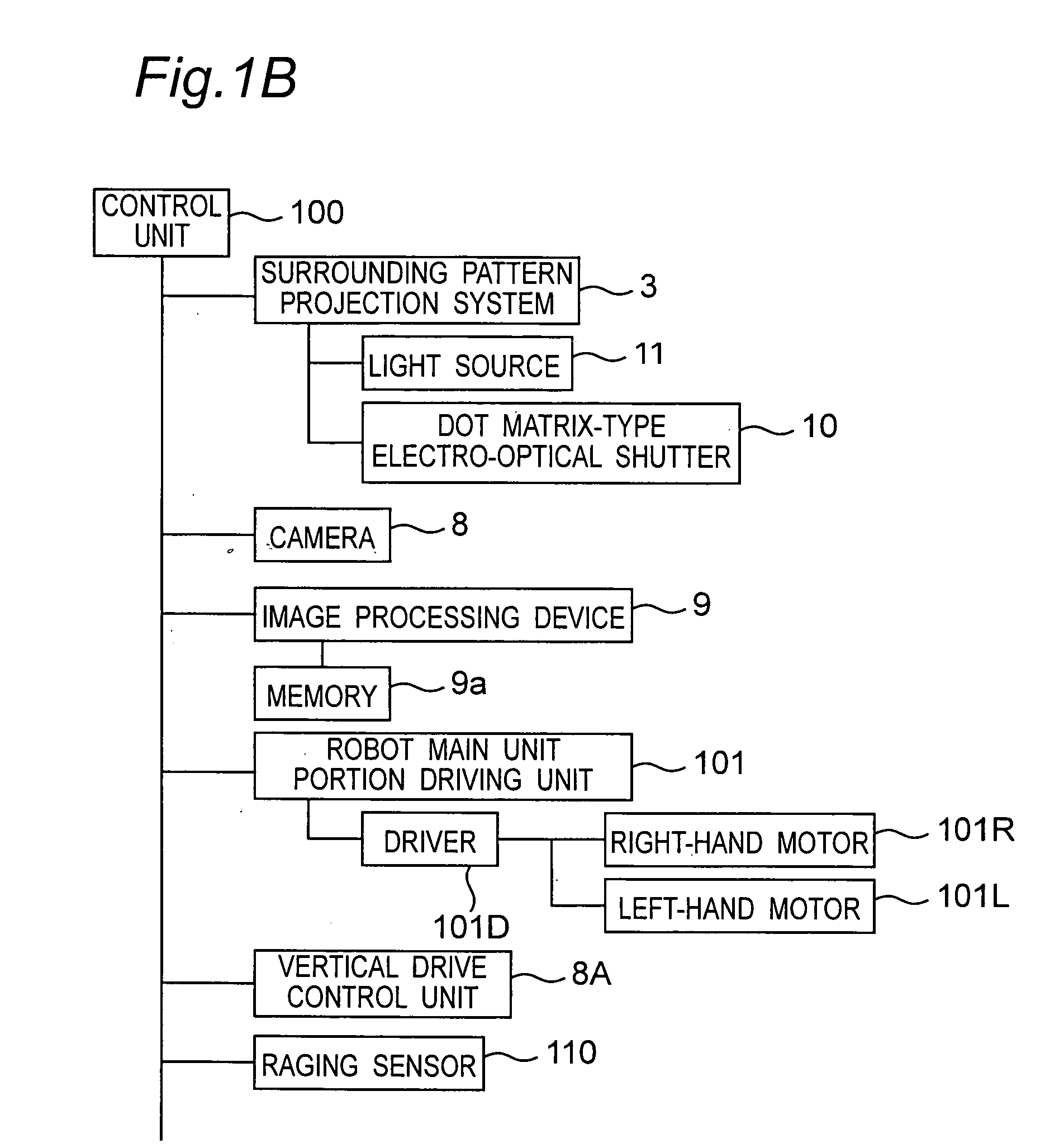
[0082] As shown in FIG. 1A, a robot 1 in the embodiment of the present invention is composed of: a main unit portion 2 of the robot 1; a surrounding pattern projection system 3 serving as one example of the projections unit and mounted on the upper portion of the main unit portion 2 in the state of being supported by a bracket-shaped projections unit support portion 4b provided to stand on the main unit portion 2, for projecting a continuous or intermittent annular pattern light beam 3a encircling the main unit portion 2 (the inner periphery of the patte...


PUM


Abstract

There are included a surrounding pattern projection system for projecting an annular pattern light beam encircling a main unit portion from an upper side of the main unit portion to a floor surface around the main unit portion in an oblique direction with respect to the floor surface, a camera for picking up a projected pattern image of the pattern light beam projected from the surrounding pattern projection system from the upper side of the main unit portion, and a image processing device for sensing a displacement of the projected image of the pattern light beam based on the picked up image picked up by the camera, the displacement being generated when the pattern light beam is projected onto a portion of an obstacle around the main unit portion which is different in height from the floor surface, and for detecting thereby the obstacle around the main unit portion.

Description

BACKGROUND OF THE INVENTION [0001] The present invention relates to a robot capable of detecting the presence of obstacles in the surrounding region, a transportation method for transporting a transportation target by using the robot, and a guiding method for guiding a guiding target to a destination by using the robot. [0002] Several methods have been proposed in the past for recognizing objects and measuring the three-dimensional shapes of the objects. For example, Patent Document 1 (U.S. Pat. No. 2,559,443). discloses a measurement method using the principle of triangulation and a measurement method involving a projection method. Hereinbelow, description will be given of these examples with reference to FIG. 8 to FIG. 12. [0003] First, the principle of triangulation is shown in FIG. 8. As shown in FIG. 8, when, in a triangle ABC, a camera is placed in a node (point) Na, a target of measurement is placed in a node Nb, and a camera is placed in a node Nc, images of the target can b...

Claims


Application Information

Patent Timeline
Patent Type & Authority Applications(United States)
IPC IPC(8): G06F19/00B25J19/04G01B11/02B25J19/06G06K9/00
CPCG06K9/00201G06V20/64
Inventor ANEZAKI, TAKASHI
Owner PANASONIC CORP
Why Eureka
Try Eureka