Dead locking deadbolt

a deadbolt and deadbolt technology, applied in the direction of mechanical control devices, keyhole guards, instruments, etc., can solve the problems of deadbolt bolts that cannot be operated by keys, deadbolts cannot be locked out,

Inactive Publication Date: 2006-03-02
MASTER LOCK COMANY LLC
View PDF43 Cites 18 Cited by
  • Summary
  • Abstract
  • Description
  • Claims
  • Application Information

AI Technical Summary

Benefits of technology

[0007] Known lock-out devices for deadbolts are unreliable, difficult and clumsy to use and have

Problems solved by technology

As a result, a mechanical member that operates the locking mechanism is restrained, thus resulting in a “lock out” of the deadbolt bolt mechanis

Method used


Image

  • Dead locking deadbolt
  • Dead locking deadbolt
  • Dead locking deadbolt

Examples


Embodiment Construction

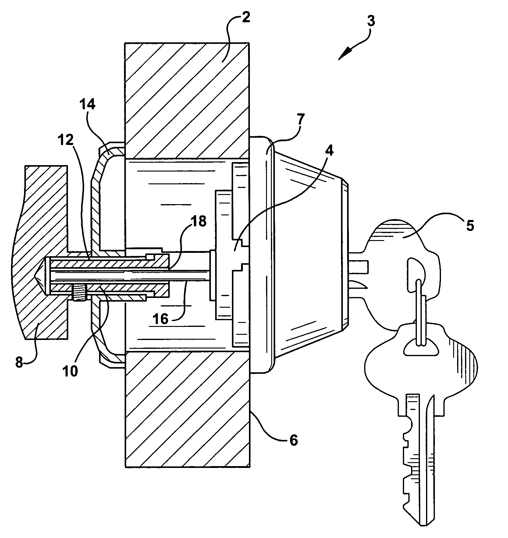
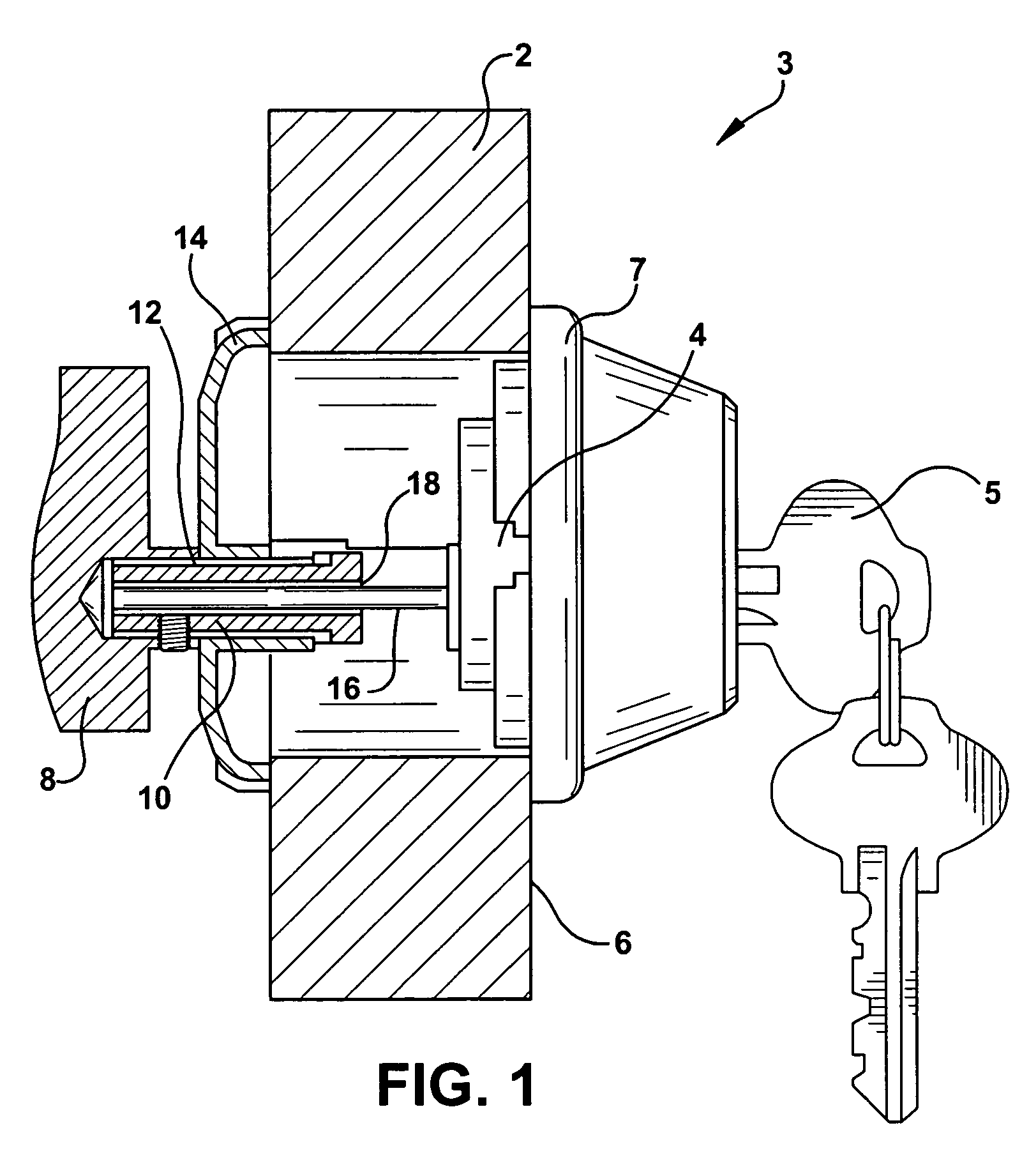
[0048] Referring now to FIG. 1, a door 2 including one embodiment of the invention is shown. As can be seen, a deadbolt manipulation mechanism, such as a conventional key cylinder 4 is mounted on one side of the door 2 which permits the deadbolt mechanism 3 to be operated by a key 5. The key cylinder 4 is normally mounted on the exterior side 6 of the door 2 in a protective housing 7. The “exterior-side” of a door is the side which is on the outside wall of a dwelling or building or any space desired to be “locked” from unauthorized entry. However, this invention is not limited to such a configuration and the key cylinder may be mounted on the interior or exterior side of the door. A second deadbolt manipulation mechanism, such as a knob or handle 8 also for operating the deadbolt is mounted on the side of the door opposite the key cylinder 4. The knob or handle 8 is mounted on a shaft 10 further described below. The shaft 10 is, in turn, mounted in an opening 12 in a shaft housing ...


PUM


Abstract

A deadbolt mechanism including a lock out mechanism that functions to disable the operation of the deadbolt from at least one side of the deadbolt mechanism. The deadbolt mechanism includes a deadbolt, key cylinder, housing, turn knob and a shaft that connects the key cylinder and turn knob. To place the deadbolt mechanism in lock out mode, a release mechanism is actuated and the turn knob is pulled outward away from the door. By pulling the knob outward, the shaft engages a portion of the housing which prevents rotation of the shaft and thereby prevents movement of the deadbolt from the lock-out position.

Description

CROSS-REFERENCE TO RELATED APPLICATIONS [0001] This non-provisional application claims the benefit of U.S. Provisional Patent Application No. 60 / 606,211, entitled “Dead Locking Deadbolt,” filed Sep. 1, 2004, and U.S. Provisional Application No. 60 / 593,462, entitled “Dead Locking Deadbolt,” filed Jan. 17, 2005.FIELD OF THE INVENTION [0002] This invention relates to locking devices in general and “lock-out” devices for deadbolts in particular. BACKGROUND OF THE INVENTION [0003] Bolts or deadbolts are well known devices for locking a door shut for security purposes. In such well-known arrangements, the deadbolt or bolt is mounted in the body of the door and the deadbolt is operated by mechanical operating devices mounted on either side of the door. When the deadbolt is operated to a locked position it typically extends or projects from the side of the door into an opening in the door jam or wall to which the door is mounted. Thus, the deadbolt when operated to an extended position, “bo...

Claims


Application Information

Patent Timeline
IPC IPC(8): E05B41/00
CPCE05B13/004Y10T70/5394Y10T70/5465Y10T70/5832Y10T70/8027Y10T292/96
Inventor SMITH, JERRYENSLOW, MIKEHACKER, DEAN D.WEBER, JOHNEBNER, TIMMARCELLE, JESSE
Owner MASTER LOCK COMANY LLC
Why Eureka
Try Eureka