Determination of correct horizontal and vertical permeabilities in a deviated well

a well and horizontal and vertical permeability technology, applied in the direction of seismology for waterlogging, borehole/well accessories, instruments, etc., can solve the problems of inability to achieve constant drawdown rate, inability to meet steady state flow condition, and difficulty in reaching constant drawdown ra

Inactive Publication Date: 2006-03-02
BAKER HUGHES INC
View PDF14 Cites 11 Cited by
  • Summary
  • Abstract
  • Description
  • Claims
  • Application Information

AI Technical Summary

Problems solved by technology

The steady state flow condition cannot be satisfied in a low permeability formation, or unless a long test time is used.
A constant drawdown rate is not reachable in practice because the tool needs time for acceleration and deceleration.
The storage effect also makes it difficult to reach a constant drawdown rate.
However, their method does not have any procedure to check if the condition of homogeneous formation can be satisfied for a real probe test.
To the best of our knowledge, there does not exist such a tool and it is probably difficult or expensive to build one.
However, there is no teaching on how to determine formation anisotropy from measurements made with a single probe.
Based on the one equation given by Proett, it would be impossible to determine two parameters with measurements from a single probe.

Method used


Image

  • Determination of correct horizontal and vertical permeabilities in a deviated well
  • Determination of correct horizontal and vertical permeabilities in a deviated well
  • Determination of correct horizontal and vertical permeabilities in a deviated well

Examples


first embodiment

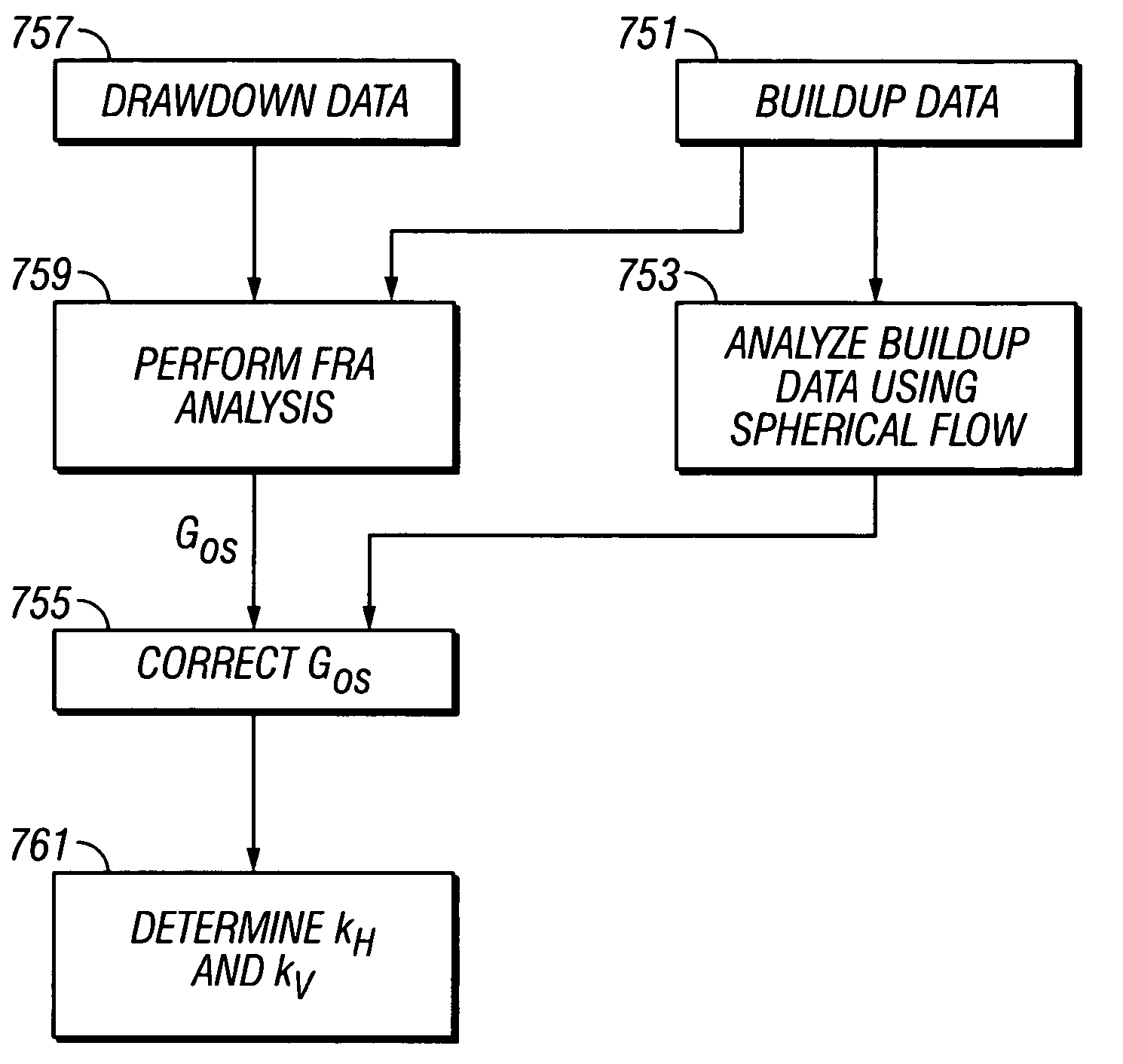
[0079]FIG. 8 is a flow chart illustrating the invention. Pressure buildup data 751 are analyzed to get a first estimate of spherical permeability. Separately, the pressure buildup data 751 and the drawdown data 757 are analyzed to get a second estimate of spherical permeability 759. Using the two different permeabilities, the geometric factor Gos for the probe is corrected 755 and using the corrected Gos, the horizontal and vertical permeabilities are determined as discussed above.

second embodiment

[0080] the present invention uses the spherical permeability obtained from the pressure buildup test (the first permeability) as a starting point for matching the entire pressure history, including the drawdown data. In Interpret2003 the geometric skin factor, sp, is used to describe the non-spherical flow near the probe. Even though the local geometry near the probe does not affect the permeability estimate, it does affect the pressure data as given by eqn. 2. In the above example, using the BU estimated permeability of 9.62 mD and an isotropic geometric skin factor of 1.95 shown in Table 1, the pressure data from Interpret2003 cannot be matched with the simulated pressure data because we used the wrong isotropic geometric skin factor. This is shown in FIG. 9 where the abscissa is time and the ordinate is pressure. The buildup portion is used to derive the permeability and this derived permeability is used to model the pressure data. More obviously, the modeled drawdown data 803 do...


PUM

PropertyMeasurementUnit
deviation angleaaaaaaaaaa
permeabilityaaaaaaaaaa
transient pressure measurementsaaaaaaaaaa

Abstract

In one method, the permeabilities are obtained by correcting the geometric factor derived from combining the FRA analysis and buildup analysis. In a second method, the permeabilities are obtained by combining the spherical permeability estimated from buildup analysis and the geometric skin factor obtained from history matching the probe-pressure data. In other methods, horizontal and vertical permeabilities are determined by analysis of pressure drawdown made with a single probe of circular aperture in a deviated borehole at two different walls of the borehole.

Description

CROSS-REFERENCES TO RELATED APPLICATIONS [0001] This application claim priority from U.S. Provisional Patent Application Ser. No. 60 / 604,552 filed on 26 Aug. 2004, the contents of which are incorporated herein by reference. This application is also a continuation-in-part of United States patent application Ser. No. 11 / 014,422 filed on Dec. 16, 2004. The application is also related to an application of the same inventors being filed concurrently under attorney docket no. 584-40072CPBACKGROUND OF THE INVENTION [0002] 1. Field of the Invention [0003] The invention is related to the field of instruments used to sample fluids contained in the pore spaces of earth formations. More specifically, the invention is related to methods of determining hydraulic properties of anisotropic earth formations by interpreting fluid pressure and flow rate measurements made by such instruments. [0004] 2. Description of the Related Art [0005] Electric wireline formation testing instruments are used to wit...

Claims


Application Information

Patent Timeline
Patent Type & Authority Applications(United States)
IPC IPC(8): E21B49/00G01N15/08
CPCG01N15/0826E21B49/008
Inventor SHENG, JAMES J.GEORGI, DANIEL T.
Owner BAKER HUGHES INC
Why Eureka
Try Eureka