Method of determination of fluid influx profile and near-wellbore space parameters

Inactive Publication Date: 2012-05-03
SCHLUMBERGER TECH CORP
View PDF2 Cites 5 Cited by
  • Summary
  • Abstract
  • Description
  • Claims
  • Application Information

AI Technical Summary

Benefits of technology

[0003]The technical result of the invention is an increased accuracy of the wellbore parame

Problems solved by technology

A disadvantage of this method is a low accuracy of the layers' relative flow rate determination

Method used


Image

  • Method of determination of fluid influx profile and near-wellbore space parameters
  • Method of determination of fluid influx profile and near-wellbore space parameters
  • Method of determination of fluid influx profile and near-wellbore space parameters

Examples


Embodiment Construction

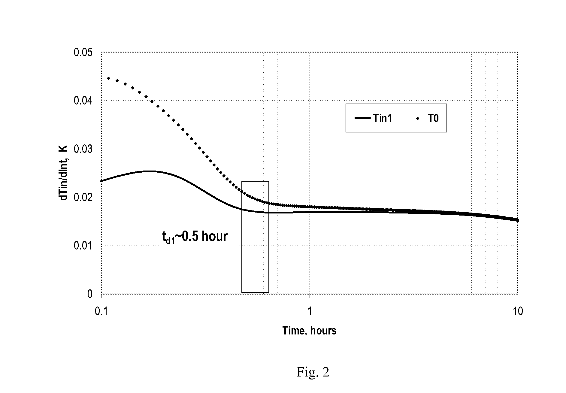
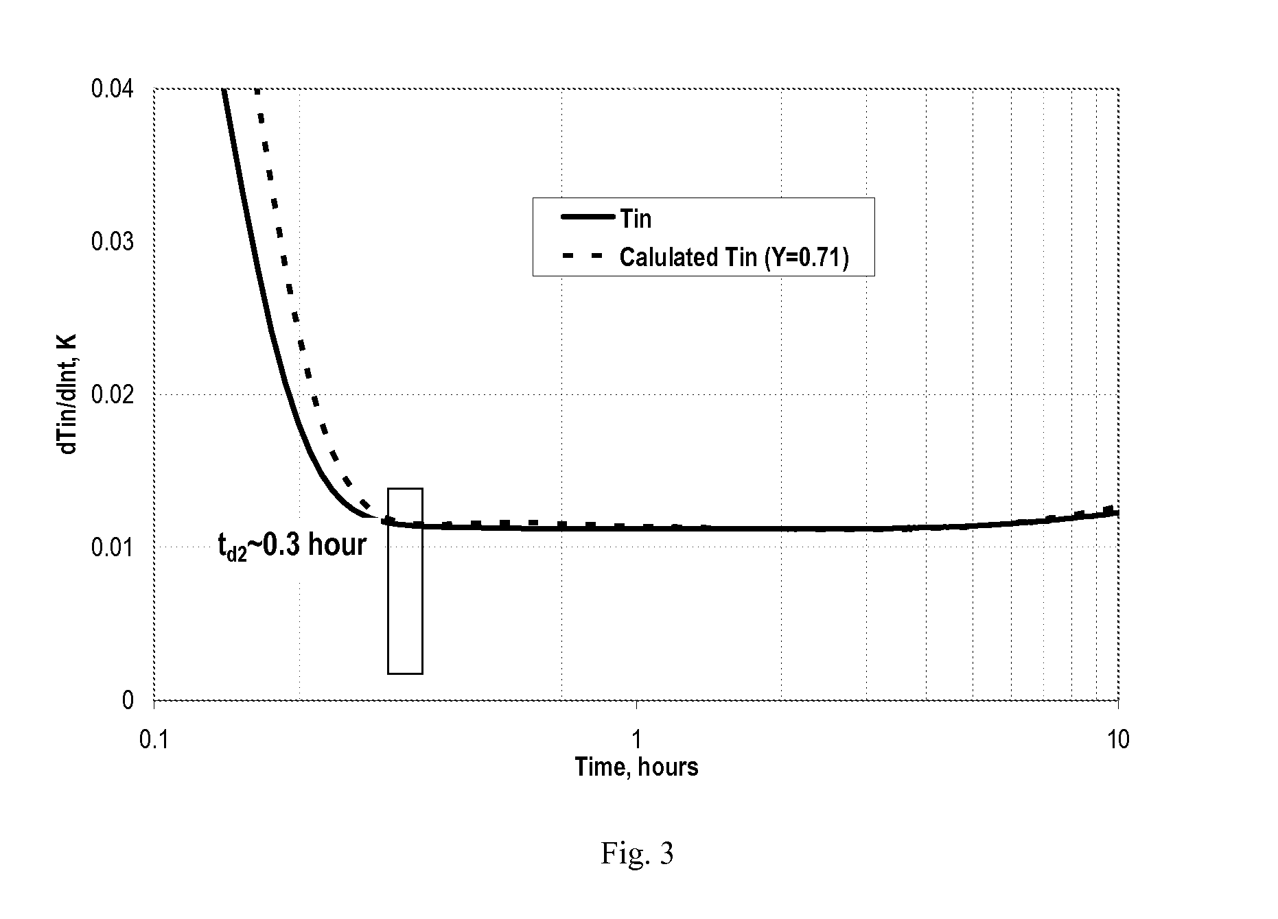
[0011]The method claimed in the invention is based on a simplified model of heat- and mass-exchange processes in the productive layer and wellbore. Let us consider the results of the model application for the processing of the measurement results of the temperature Tin(i)(t) of fluids flowing into the wellbore from two productive layers.

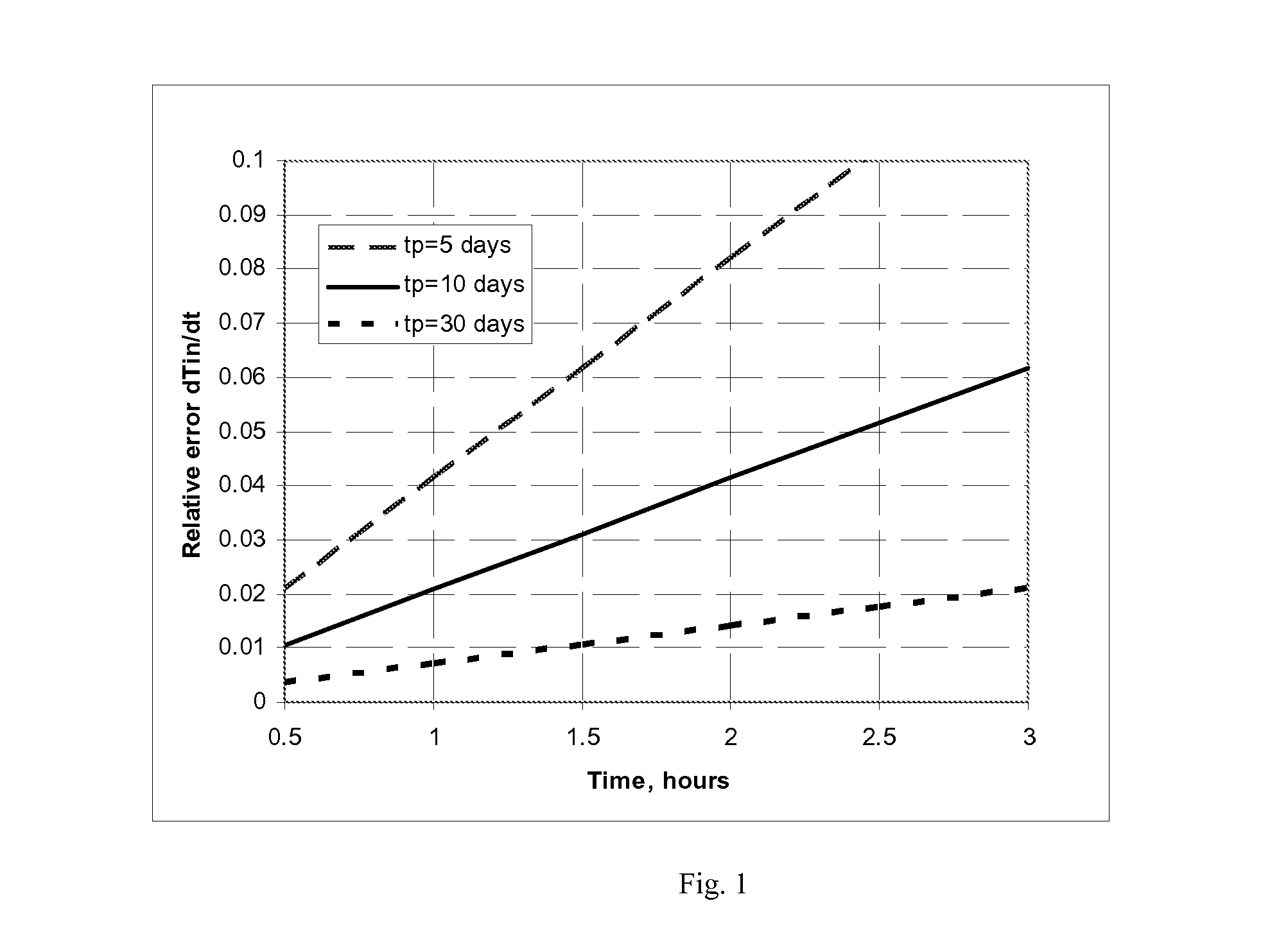
[0012]In the approximation of the productive layers' pressure stabilization, the change rate in the temperature of the fluid flowing into the wellbore after the production rate has been changed is described by Equation (1):

Tint=ɛ02·(s+θ)·[Pe-P1f(t,td1)·1(δ12·tp+t2+t)+P1-P2f(t,td)·1(t2+t)],(1)

[0013]where Pe is a layer pressure, P1 and P2—bottomhole pressures before and after the change in the production rate, s—a layer skin factor, θ=ln(re / rw), re—a drain radius, rw—the wellbore radius, t—time counted from the moment of the change in the production rate, tp—production time at the bottomhole pressure of

P1,δ12=Pe-P1Pe-P2,f(t,td)={Kt≤td1tdt,K=kdk=[1+sθd]...


PUM


Abstract

Method for determination of a fluid influx profile and near-wellbore area parameters comprises measuring a first bottomhole pressure and after operating a well at a constant production rate changing the production rate and measuring a second bottomhole pressure. A wellbore fluid temperature over an upper boundary of a lowest productive layer and wellbore fluid temperatures above and below other productive layers are measured and relative production rates and skin factors of the productive layers are calculated from measured wellbore fluid temperatures and measured first and second bottomhole pressures.

Description

FIELD OF THE DISCLOSURE[0001]The invention relates to the area of geophysical studies of oil and gas wells, particularly, to the determination of the fluid influx profile and multi-layered reservoir near-wellbore area space parameters.BACKGROUND OF THE DISCLOSURE[0002]A method to determine relative production rates of the productive layers using quasi-steady flux temperature values measured along the wellbore is described, e.g. in: {hacek over (C)}eremenskij G.A. Prikladnaja geotermija, Nedra, 1977 p. 181. A disadvantage of this method is a low accuracy of the layers' relative flow rate determination resulting from the assumption of the Joule-Thomson effect constant value for different layers. In effect, it depends on the formation pressure and specific layer pressure values.SUMMARY OF THE DISCLOSURE[0003]The technical result of the invention is an increased accuracy of the wellbore parameters (influx profile, values of skin factors for different productive layers) determination.[00...

Claims


Application Information

Patent Timeline
IPC IPC(8): E21B47/06
CPCE21B43/14E21B49/008E21B47/1005E21B47/06E21B47/103
Inventor SHAKO, VALERY VASILIEVICHPIMENOV, VYACHESLAV PAVLOVICHKUCHUK, FIKRI JOHN
Owner SCHLUMBERGER TECH CORP
Why Eureka
Try Eureka