
Mask, mask shell and seal with improved mounting, mask seal, method of mask manufacture and mask with reduced exhalation noise

Inactive Publication Date: 2006-03-02
VITAL SIGNS INC
View PDF23 Cites 268 Cited by
  • Summary
  • Abstract
  • Description
  • Claims
  • Application Information

AI Technical Summary

Benefits of technology

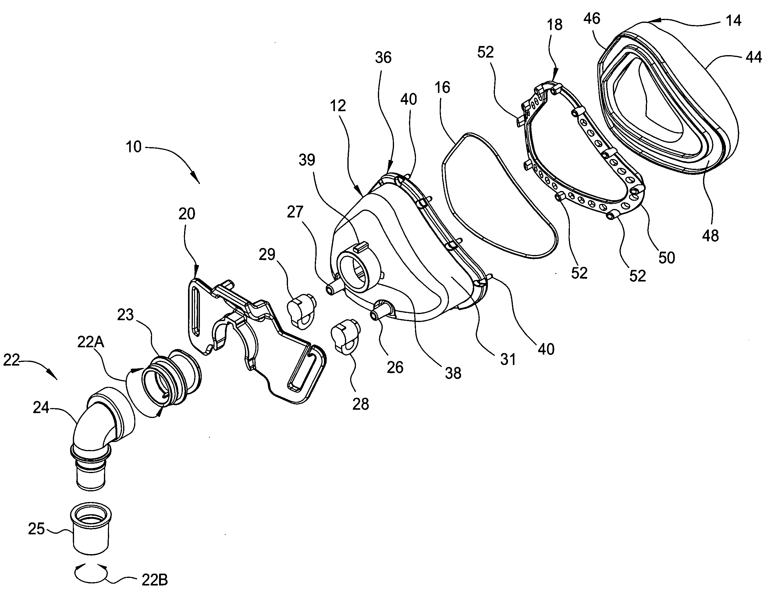
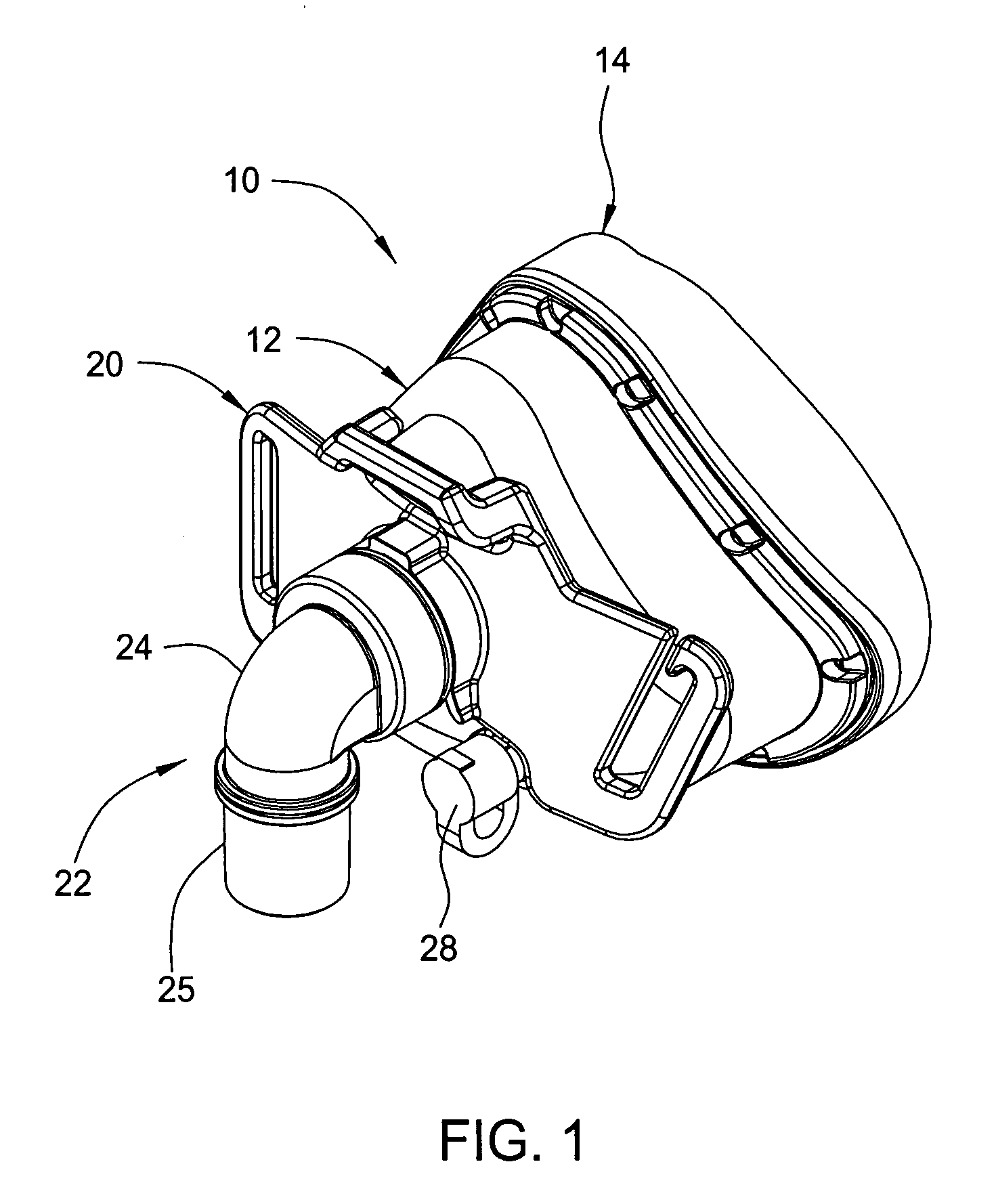
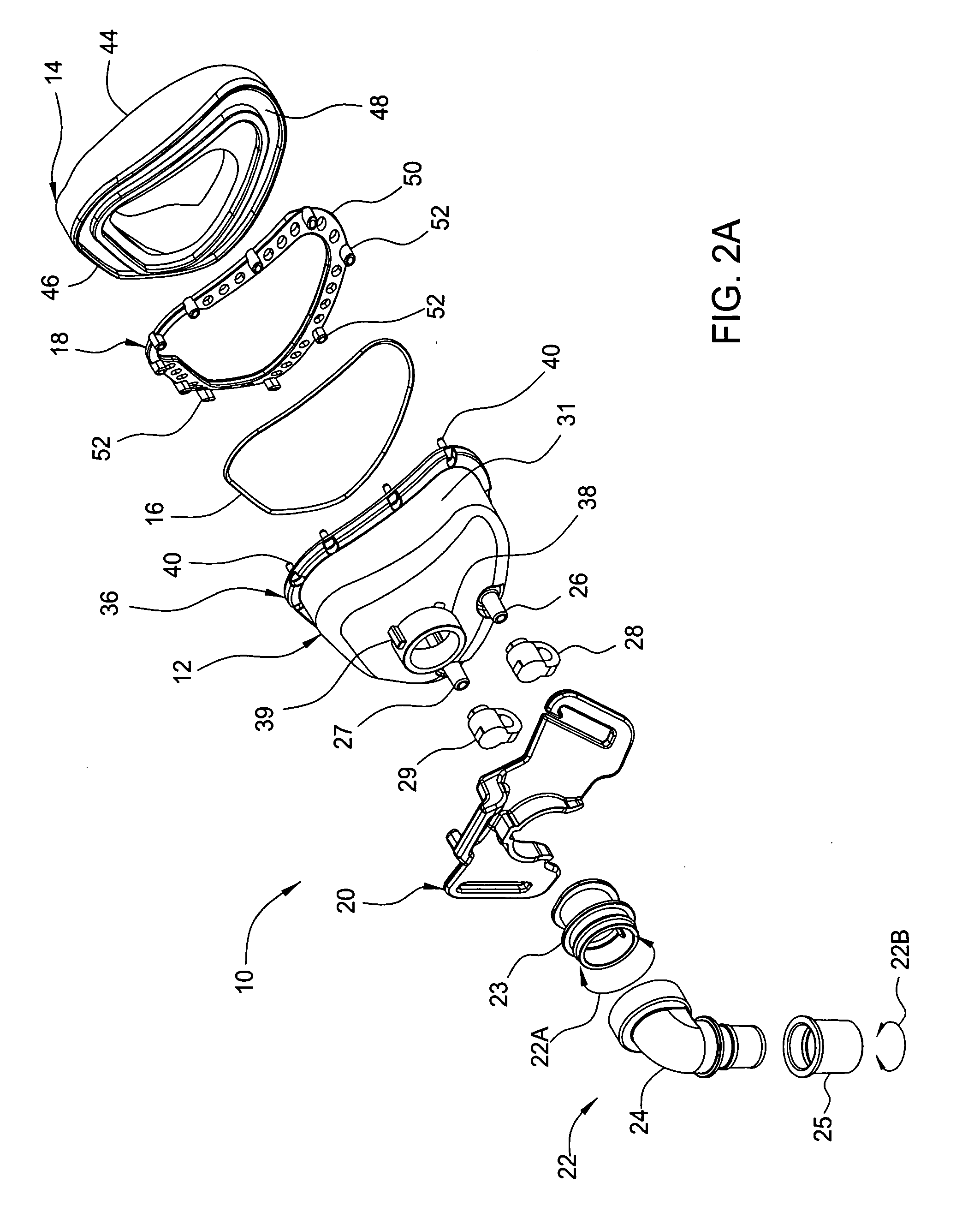
[0011] A mask including a shell provided with shell mounting members and a seal provided with seal mounting members for engaging the shell mounting members to mount the seal to the shell, method of manufacturing a mask including such mask shell and seal, a mask including a plurality of headstraps and a headstrap retention bracket mounted to the headstrap for mounting the headstraps removably to a mask, a mask seal of generally hollow triangular soft resilient material including a peripheral portion and a generally hollow triangular seal mounting member embedded in the seal peripheral portion and for mounting the seal to a mask shell, a mask shell having a deformable malleable member in its peripheral portion which may be deformed to customize the mask seal to a person's face and a mask with a plurality of angular vent holes for reducing the noise of a mask wearer's exhaled breath and for directing the exhaled breath away substantially parallel to the mask wearer's body.

Problems solved by technology

Such prior art venting can produce a noisy or turbulent air flow or jet of air which can impinge annoyingly on the mask wearer or onto nearby persons such as a sleep partner.
This loosening and re-tightening of the headstraps is known to be quite annoying.
Further, the mask, particularly the seal, must be cleaned and since, as noted, the mask is typically mounted fixedly to the headstraps, this makes cleaning more difficult than is desirable.
Further, the cleaning of a mask or seal mounted fixedly to the headstraps can cause the headstraps to become wet and possibly suffer shrinkage or at least some structural or functional impairment.
These prior art seal structures are generally known to be costly to manufacture.

Method used


Image

  • Mask, mask shell and seal with improved mounting, mask seal, method of mask manufacture and mask with reduced exhalation noise
  • Mask, mask shell and seal with improved mounting, mask seal, method of mask manufacture and mask with reduced exhalation noise
  • Mask, mask shell and seal with improved mounting, mask seal, method of mask manufacture and mask with reduced exhalation noise

Examples


Embodiment Construction

[0034] An embodiment of the mask of the present invention is shown in the drawings and indicated by general numerical designation 10. It will be understood that the mask 10 is dimensioned to be a nasal mask particularly useful as a nasal CPAP mask, but it will be still further understood that the mask of the present invention also may be embodied as other masks such as, for example and not by way of limitation, a full face mask.

[0035] The mask 10, referring particularly to FIGS. 1 and 2A-2D, includes a mask shell indicated by general numerical designation 12, a mask seal indicated by general numerical designation 14, a hollow generally triangular malleable member 16, a hollow generally triangular seal mounting member indicated by general numerical designation 18, a head strap retention bracket indicated by general numerical designation 20, and a dual swivel indicated by general numerical designation 22 and of the type known to the art for providing swiveling in two directions as in...


PUM


Abstract

A mask, a mask shell and seal provided with cooperative mounting members for mounting the seal to the shell, method of manufacturing such mask, mask shell and seal, a mask including a plurality of headstraps and a headstrap retention bracket for mounting the headstraps removably to the mask, a mask seal including an embedded seal mounting member for mounting the seal to a mask shell, a mask shell including a malleable member in its peripheral portion which may be deformed to customize the mask seal to a person's face, and a mask with a plurality of angular vent holes for reducing the noise of a mask wearer's exhaled breath and for directing the exhaled breath away substantially parallel to the mask wearer's body.

Description

BACKGROUND OF THE INVENTION [0001] This invention relates generally to masks for supplying breathable gas to a person, and more particularly, relates to a nasal CPAP (Continuous Positive Airway Pressure) mask particularly useful for supplying pressurized breathing gas, such as oxygen, to a person in the treatment of obstructive sleep apnea. [0002] The prior art is replete with masks which are of many different sizes, structures and for use in many different applications. Many different full face masks covering both the nose and the mouth are known to the art, and many different nasal masks covering only the nose are known to the art. A typical mask may include a shell of relatively hard or stiff material and a seal mounted to the shell and for conforming to the contours of a person's face, surrounding the nose and / or mouth, and for engaging such contours in an air-tight or sealing engagement. Such shell and seal may be made of numerous materials known to the art and also known to th...

Claims


Application Information

Patent Timeline
IPC IPC(8): A62B18/08
CPCA61M16/06A61M2205/42A61M16/0683A61M16/0825A61M16/0858
Inventor GEIST, LEROY D.
Owner VITAL SIGNS INC
Learn More