

Fuel cut-off valve
- Summary
- Abstract
- Description
- Claims
- Application Information
AI Technical Summary
Benefits of technology
Problems solved by technology
Method used
Image

Examples
first embodiment
A. First Embodiment
(1) General Structure of Fuel Cut-Off Valve 100
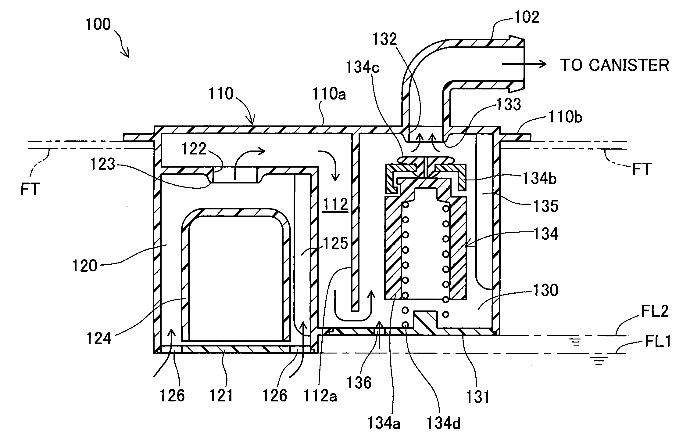
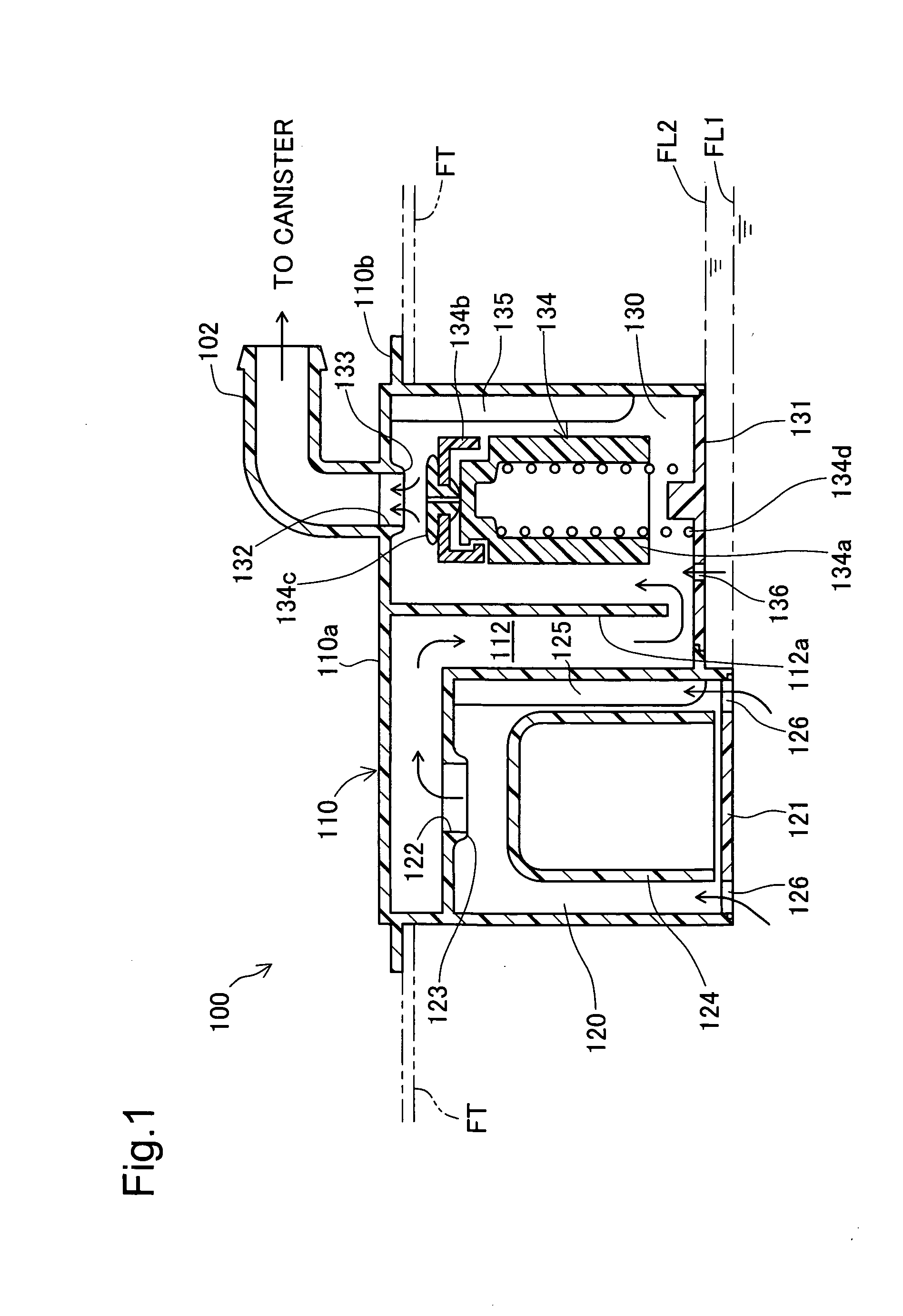
[0031]FIG. 1 is a sectional view schematically illustrating the structure of a fuel cut-off valve 100 attached to an upper portion of a fuel tank FT of an automobile (not shown) in a first embodiment of the invention. In the structure of this embodiment, the fuel cut-off valve 100 is set on an upper wall of the fuel tank FT made of a polyethylene-containing complex resin material. The fuel cut-off valve 100 has a canister connection port 102 that is exposed outside the fuel tank FT and is connected to a canister (not shown). The fuel cut-off valve 100 may be designed as an inner tank type to be wholly built in the fuel tank FT.
[0032] In the refueling process, the fuel cut-off valve 100 partly closes with only a narrow opening left for ventilation when the fuel level in the fuel tank FT rises to a preset first level FL1. The fuel cut-off valve 100 completely closes to prevent an outflow of the liquid fuel to the cani...
second embodiment
B. Second Embodiment
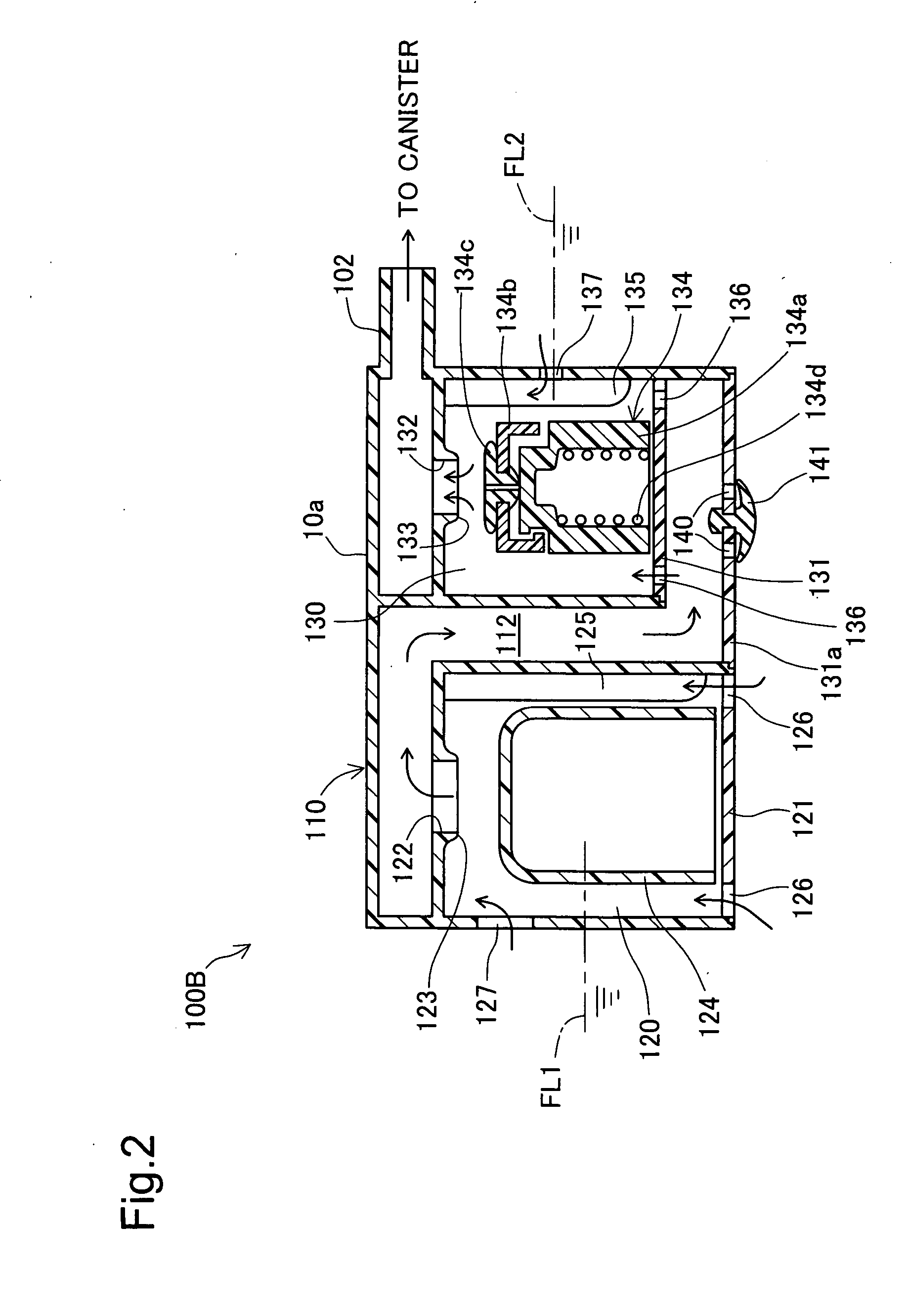
[0056]FIG. 2 is a sectional view schematically illustrating the structure of another fuel cut-off valve 100B in a second embodiment of the invention. The primary difference of the second embodiment from the first embodiment is the state of change in fuel level in the first valve chest 120 and the second valve chest 130. The fuel cut-off valve 100B of the second embodiment has a large-diameter side through hole 127 formed in a side wall of the first valve chest 120 and a small-diameter side through hole 137 formed in a side wall of the second valve chest 130. The second valve chest plate 131 is located inside the valve casing 110 to define the second valve chest 130. A casing bottom wall 131a of valve casing 110 has a bottom through hole 140 and an umbrella valve 141 to open and close the bottom through hole 140. The fuel cut-off valve 100B of this embodiment is designed as an inner tank type. The canister connection port 102 is protruded from a side wall of the u...
third embodiment
C. Third Embodiment
[0063]FIG. 3 is a sectional view schematically illustrating the structure of still another fuel cut-off valve 100C in a third embodiment of the invention. The fuel cut-off valve 100C of this embodiment is also designed as an inner tank type and has the similar structure to that of the fuel cut-off valve 100 of the first embodiment, except the design of the inter-valve chest flow passage 112 connecting the first valve chest 120 to the second valve chest 130 and the presence of an inner-tank connection aperture 150. In the fuel cut-off valve 100C of the third embodiment, the inter-valve chest flow passage 112 is formed along the first valve chest 120 and the second valve chest 130 and communicates with the upper end of the second valve chest 130. The inner-tank connection aperture 150 is located above the second valve chest 130 and is formed at a position closest to the upper wall of the fuel tank FT. The inner-tank connection aperture 150 connects the second valve ...
PUM
 Abstract
Description
Claims
Application Information