
Image capture apparatus and control method therefor

a technology of image capture and control method, applied in the field of signal processing method, can solve the problems of affecting the light amount control, reflected light amount, and difficulty in accurately detecting the face of the person from the captured imag

Inactive Publication Date: 2006-03-02
CANON KK
View PDF9 Cites 49 Cited by
  • Summary
  • Abstract
  • Description
  • Claims
  • Application Information

AI Technical Summary

Benefits of technology

[0012] At least one exemplary embodiment relates to an image capture apparatus configured to perform light emission control facilitating the image capturing of a face area of a subject. In at least one exemplary embodiment of the image capture apparatus, respective face areas of the subject are detected from captured image signals acquired before and after preliminary light emission, and a luminance comparison calculation is performed between the detected face areas from the captured image signals, so that light amount control can be performed in an area centered on the face area of the subject.

Problems solved by technology

Hence, in a case where there exists a subject having a high or low reflectance within an image frame, the amount of reflected light can adversely affect the light amount control.
However, for example, under the circumstance where luminance is not sufficient (in a case where a person is photographed with a night view for a background), it is difficult to accurately detect the face of the person from the captured image.
However, typically detection accuracy is deteriorated in darkness in conventional methods.

Method used


Image

  • Image capture apparatus and control method therefor
  • Image capture apparatus and control method therefor
  • Image capture apparatus and control method therefor

Examples


first exemplary embodiment

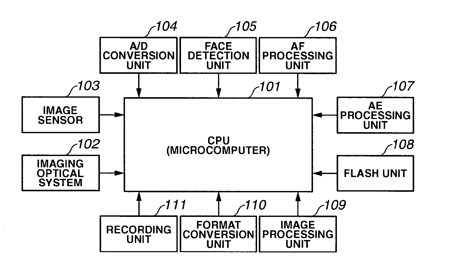
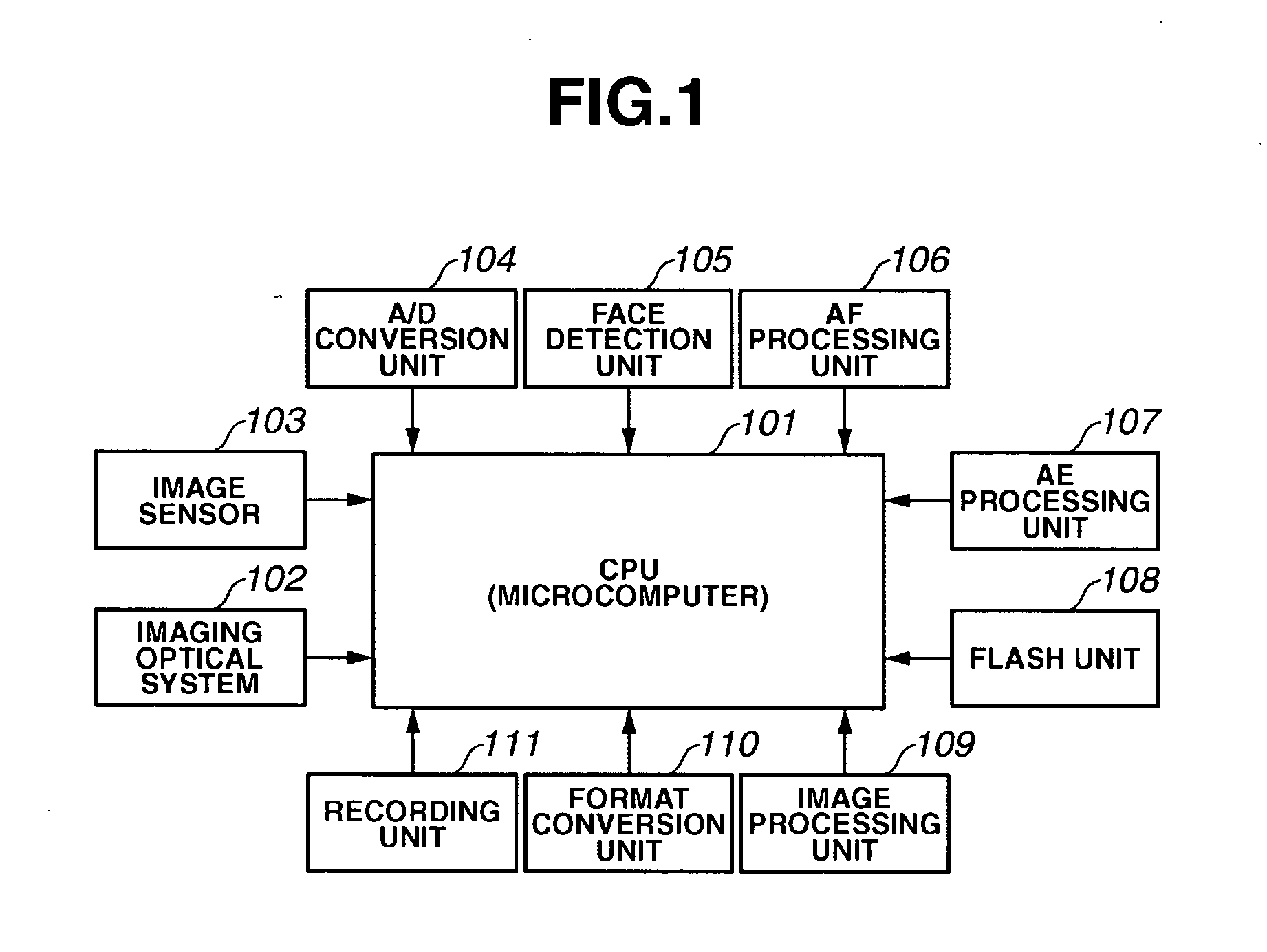
[0029]FIG. 1 illustrates a block diagram of an image capture apparatus according to a first exemplary embodiment.

[0030] In FIG. 1, reference numeral 101 denotes a CPU (central processing unit) (e.g., a microcomputer, or microprocessor (e.g., Pentium 4)) configured to perform various controls for the image capture apparatus (e.g., camera). Reference numeral 102 denotes an imaging optical system (e.g., a system including a lens, a diaphragm, a shutter), and reference numeral 103 denotes an image sensor (e.g., a CCD (charge-coupled device) having a photoelectric conversion function, other image sensors as known by one of ordinary skill in the relevant arts, and equivalents) Reference numeral 104 denotes an A / D conversion unit configured to convert an analog signal acquired from the image sensor 103 into a digital signal. Reference numeral 105 denotes a face detection unit configured to detect face information (e.g., area, shape, position) of the face of a subject from image data gener...

second exemplary embodiment

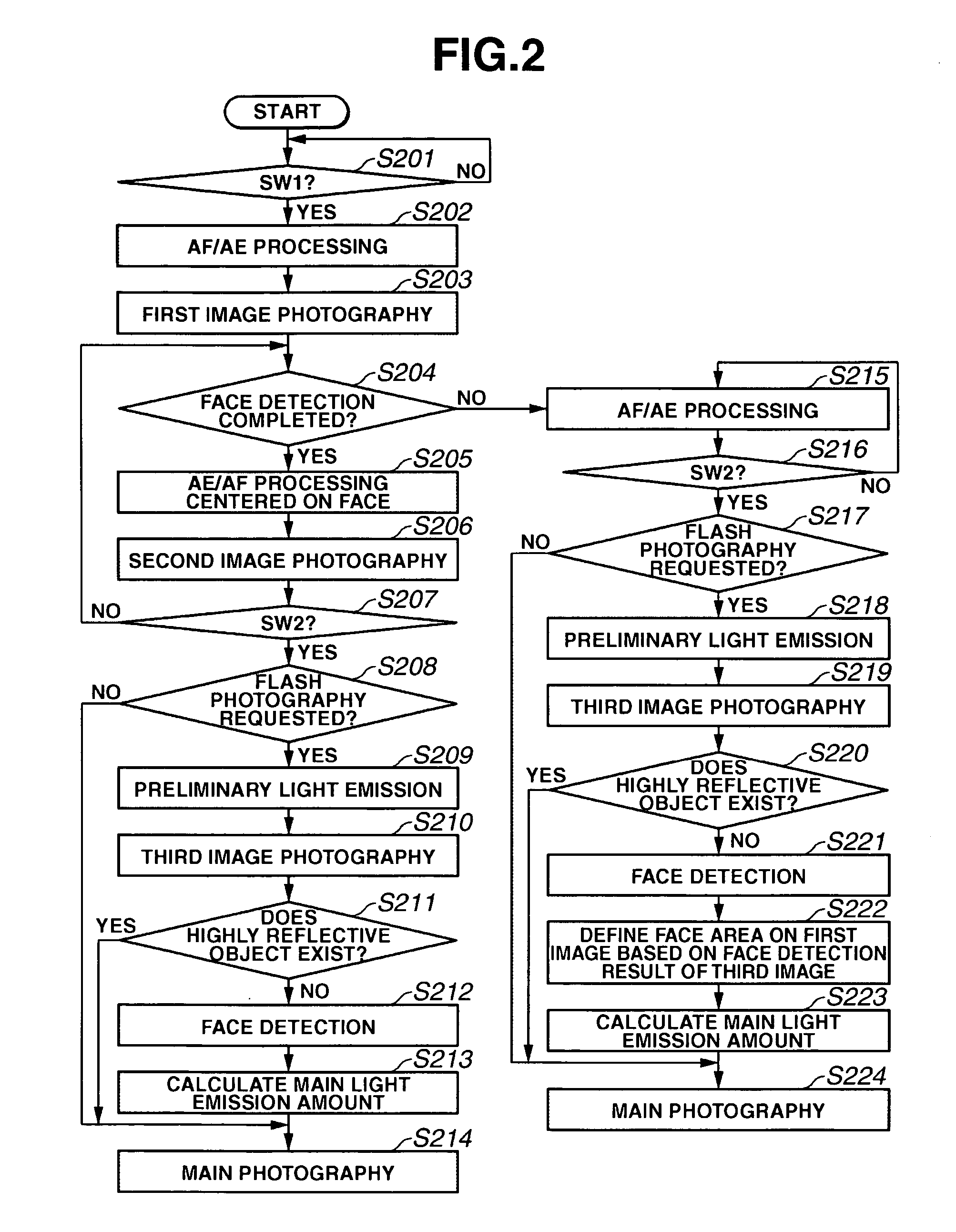
[0080]FIG. 5 illustrates a flowchart explaining of the process steps in an image capture apparatus according to a second exemplary embodiment.

[0081] The operation of the second exemplary embodiment will be described by using the flowchart of FIG. 5.

[0082] In FIG. 5, the steps for performing the same process as the first exemplary embodiment are allotted the same step numbers.

[0083] The second exemplary embodiment, differs from the first exemplary embodiment by the inclusion of additional steps related to the setting of weighting coefficients (steps S301 and S302) to the face area. The differing steps of the second exemplary embodiment will be described below.

[0084] Here, similar to the first exemplary embodiment, at step S212, the face detection unit 105 can perform face detection for the third image data acquired at step S210, and acquire face information (e.g., face area, face position, reflected light data) and, then, the process proceeds to step S301.

[0085] At step S301, th...


PUM


Abstract

At least one exemplary embodiment can control light emission so as to facilitate a face area of a subject to be adequately photographed. In the at least one exemplary embodiment, respective face areas of the subject can be detected from captured image signals acquired before and after preliminary light emission, and a luminance comparison calculation can be performed between the detected face areas from the captured image signals, so that light amount control can be performed in an area centered on the face area of the subject.

Description

BACKGROUND OF THE INVENTION [0001] 1. Field of the Invention [0002] The present invention relates to a signal processing method. More particularly, though not exclusively, a signal processing method for a digital camera and / or a video camera, using an image sensor. [0003] 2. Description of the Related Art [0004] In a conventional image capture apparatus, light amount control is performed based on data on an amount of reflected light from a subject within an image frame at the time of flash photography. [0005] Hence, in a case where there exists a subject having a high or low reflectance within an image frame, the amount of reflected light can adversely affect the light amount control. [0006] For example, in a case where a subject puts on black clothes, if the conventional system is employed, since light amount control is performed based on data on an amount of reflected light from the subject within an image frame, the face of the subject is illuminated with more than an adequate am...

Claims


Application Information

Patent Timeline
Patent Type & Authority Applications(United States)
IPC IPC(8): H04N9/68G03B7/16G03B15/05G06T1/00G06T5/50H04N23/75H04N101/00
CPCH04N5/2354H04N23/74H04N23/70H04N23/75
Inventor MIYAZAKI, YASUYOSHI
Owner CANON KK
Learn More