Nuclear fuel assembly protective grid

a protective grid and fuel assembly technology, applied in nuclear elements, nuclear engineering problems, greenhouse gas reduction, etc., can solve the problems of fuel assembly damage due to debris, chip and metal particles still remain hidden in the system, and debris tends to lodge in the grid

Active Publication Date: 2006-03-02
WESTINGHOUSE ELECTRIC CORP
View PDF15 Cites 35 Cited by
  • Summary
  • Abstract
  • Description
  • Claims
  • Application Information

AI Technical Summary

Benefits of technology

[0008] The protective grid of this invention can be formed as a stand alone component or can be constructed from wider integral straps that combine the structure of the debris filtering grid of this invention with the structure of a conventional grid. The debris filter lowermost grid of this invention preferably works in combination with the debris filter bottom nozzle described in co-pending application Ser. No. 10 / 751,349, filed Jan. 5, 2004 (attorney docket ARF 2004-003).

Problems solved by technology

Although elaborate procedures are carried out to help assure debris removal, experience shows that in spite of the safeguards used to effect such removal, some chips and metal particles still remain hidden in the systems.
In particular, fuel assembly damage due to debris trapped at the lowermost grid has been noted in several reactors in recent years.
The debris tends to become lodged in the lowermost support grid of the fuel assembly within the spaces between the “egg crate” shaped cell walls of the grid and the lower end portions of the fuel rod tubes.
The damage consists of fuel rod tube perforations caused by fretting of the debris in contact with the exterior of the tube.
Debris also becomes entangled in the nozzle plate holes and the flowing coolant causes the debris to gyrate, which tends to cut through the cladding of the fuel rods.

Method used


Image

  • Nuclear fuel assembly protective grid
  • Nuclear fuel assembly protective grid
  • Nuclear fuel assembly protective grid

Examples


Embodiment Construction

[0015] In the following description, like reference characters designate like or corresponding parts throughout the several views of the drawings. Also in the following description, it is to be understood that such terms as “forward”, “rearward”, “left”, “right”, “upwardly”, “downwardly” and the like are words of convenience and are not to be construed as limiting terms.

Fuel Assembly

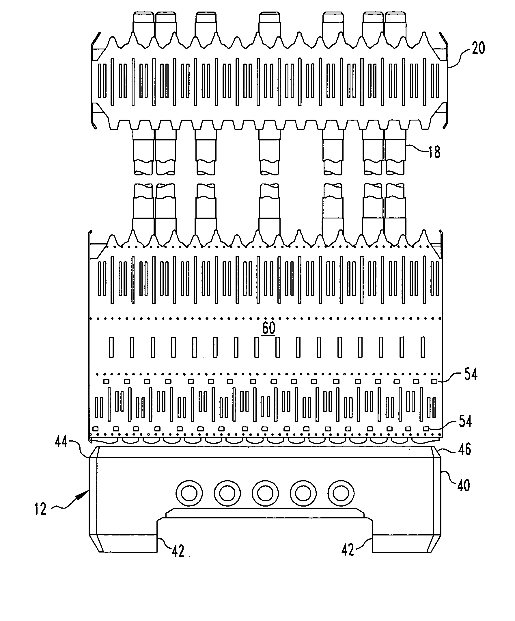
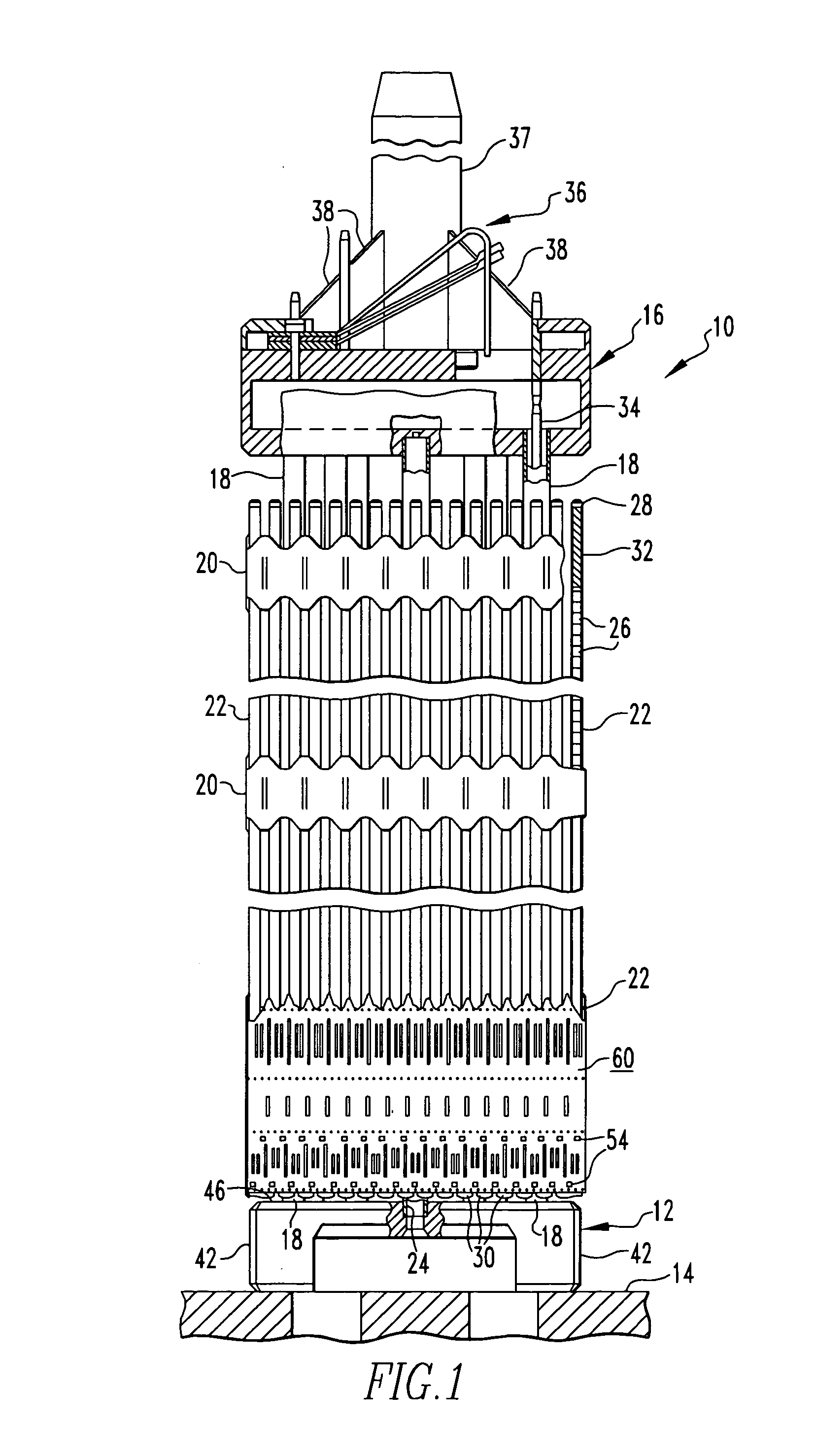
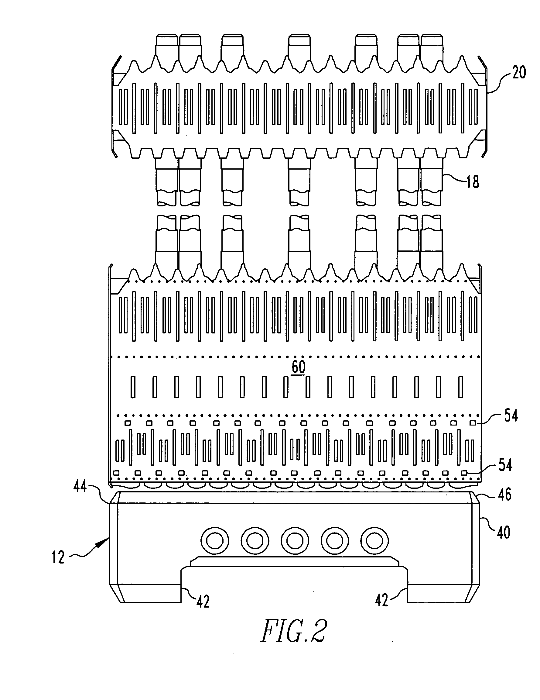
[0016] Referring now to the drawings and particularly to FIG. 1, there is shown an elevational view of the fuel assembly, represented in vertically shortened form and being generally designated by reference numeral 10. The fuel assembly 10 is the type used in a pressurized water reactor and has a structural skeleton which, at its lower end, includes the debris filter bottom nozzle 12, which is described more fully in co-pending patent application Ser. No. 10 / 751,349 (attorney docket ARF 2004-003). The bottom nozzle 12 supports the fuel assembly 10 on a lower core support plate 14 in the core region of...


PUM


Abstract

An integral multilevel debris-catching system for a nuclear reactor fuel assembly having a lower protective grid incorporating laterally offset debris-catching arches at several elevations, extended solid fuel rod bottom end plugs and a bottom debris-filtering nozzle. Dimples and opposing opposite springs and the debris-trapping arches, which are spaced from the end plugs, are all located at elevations below the fuel cladding.

Description

BACKGROUND OF THE INVENTION [0001] 1. Field of the Invention [0002] The present invention relates generally to nuclear reactors and, more particularly, is concerned with a debris filter grid for a nuclear fuel assembly. [0003] 2. Related Art [0004] During manufacturing, subsequent installation and repair of components of a nuclear reactor coolant circulation system, diligent effort is made to help assure removal of all debris from the reactor vessel and its associated systems, which circulate coolant throughout the primary reactor coolant loop under various operating conditions. Although elaborate procedures are carried out to help assure debris removal, experience shows that in spite of the safeguards used to effect such removal, some chips and metal particles still remain hidden in the systems. Most of the debris consists of metal turnings, which were probably left in the primary system after steam generator repair or replacement. [0005] In particular, fuel assembly damage due to ...

Claims


Application Information

Patent Timeline
Patent Type & Authority Applications(United States)
IPC IPC(8): G21C3/34
CPCG21C3/3206G21C3/34G21Y2002/201Y02E30/40G21Y2002/304G21Y2004/30G21Y2002/207Y02E30/30
Inventor LEE, YU CHUNGSPARROW, JAMES ALAN
Owner WESTINGHOUSE ELECTRIC CORP
Why Eureka
Try Eureka