Fiber bundles and methods of making fiber bundles

a fiber bundle and bundle technology, applied in the direction of bundled fibre light guides, instruments, optical elements, etc., can solve the problems of physical fraying of the fiber bundle, affecting the light affecting the transmission of the beam, so as to achieve the effect of convenient fixture in the devi

Active Publication Date: 2006-03-02
CORNING INC
View PDF45 Cites 71 Cited by
  • Summary
  • Abstract
  • Description
  • Claims
  • Application Information

AI Technical Summary

Benefits of technology

[0013] The devices and methods of the present invention result in a number of advantages over prior art devices and methods. For example, the fiber bundles of the present invention can be made to be durable and handleable, and easily fixtured in a device. Embodiments of the present invention having a lower index glass tube can provide an output beam having a desired numerical aperture. The methods of the present invention allow the skilled artisan to construct fiber bundles having a large number of optical fibers in a desired, well-controlled geometrical arrangement.

Problems solved by technology

However, conventional fiber bundles have certain disadvantages.
For example, especially in tapered fiber bundles, the terminal section of the fiber bundle is often very small and very fragile, making it difficult to handle and prone to breakage.
Further, the outermost fibers of a conventional fiber bundle can separate from the interior fibers, causing both a physical fraying of the fiber bundle, and a corresponding fraying of the optical beam.
Since it is difficult to remove airspace between fibers at the endface of the fiber bundle, polishing and AR coating of the endface can be complicated by the presence of particulate matter in any airspace.

Method used


Image

  • Fiber bundles and methods of making fiber bundles
  • Fiber bundles and methods of making fiber bundles
  • Fiber bundles and methods of making fiber bundles

Examples


example

[0059] The present invention is further described by the following non-limiting example.

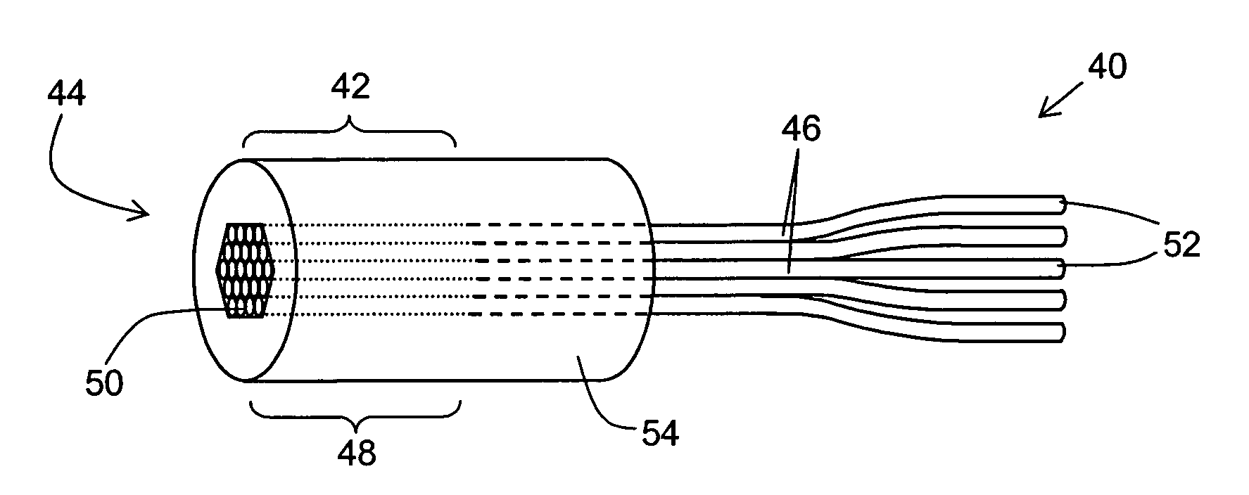
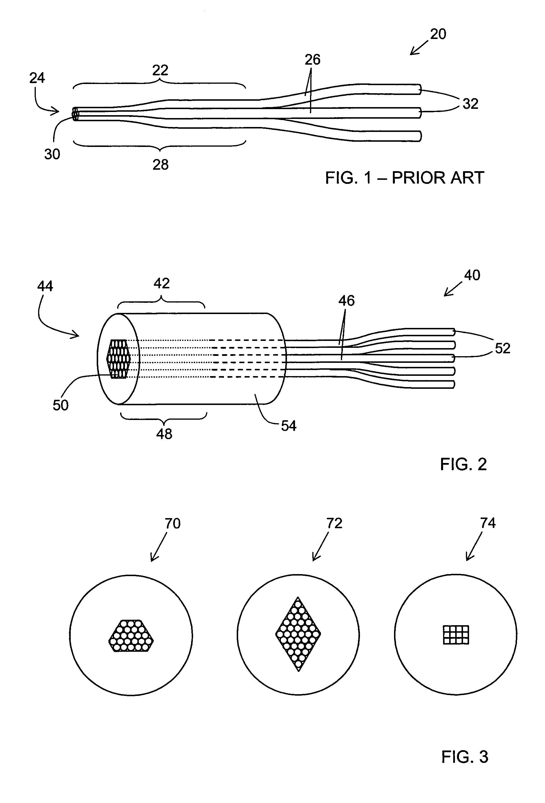
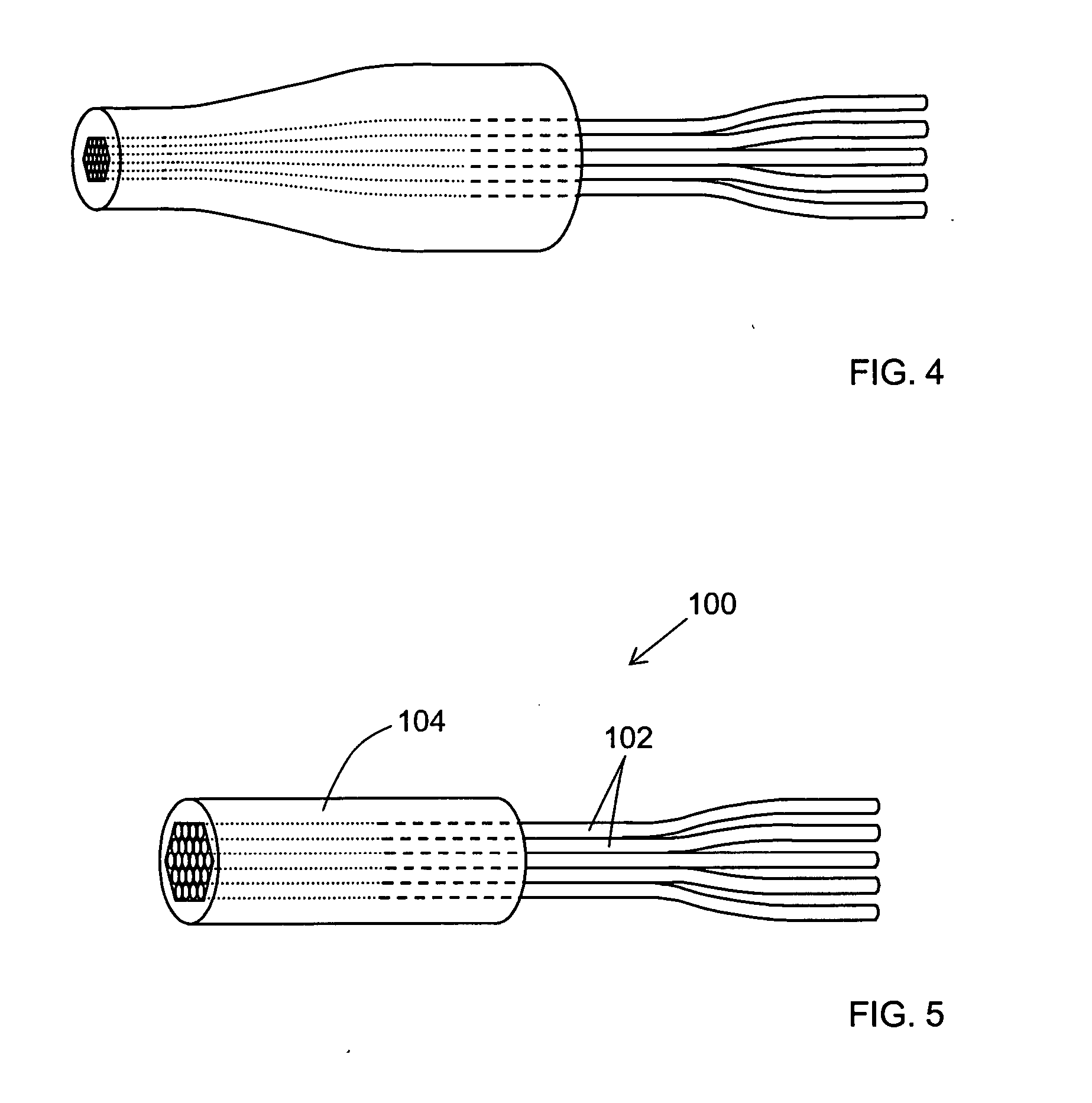
[0060] Twenty three coated multimode optical fibers (made from silica glass with dopants to control refractive index) were inserted into a cellular arrangement tool (about 15 mm wide) made using the stack-and-draw methods used to make photonic band gap fibers and having the irregular hexagonal geometry of fused fiber bundle 70 in FIG. 3, with cells large enough (˜270 μm) to accommodate the coated optical fibers. The cellular arrangement tool was mounted on a movable stage (with possible adjustments in three linear dimensions and rotationally around the vertical axis). The glass tube (silica with about 6% boron dopant) had an inner bore with the irregular hexagonal geometry, just large enough to fit the 23 optical fibers (with a tolerance of ˜1% or less), and was also mounted on a movable stage. The glass tube about 50 mm long, and was beveled at an angle of about 45°, and the cellular alignment ...


PUM

PropertyMeasurementUnit
refractive indexaaaaaaaaaa
cross-sectional areaaaaaaaaaaa
bevel angleaaaaaaaaaa

Abstract

The present invention relates to fiber bundles and methods for making fiber bundles. According to one embodiment of the invention, at the endface of the fused fiber bundle, the ratio of the cross-sectional area of the endface to the cross sectional area of the plurality of optical fibers is at least about 2.5. According to another embodiment of the invention, a fused fiber bundle includes a plurality of optical fibers, and a glass tube surrounding the terminal segments of the optical fibers, wherein the refractive index of the glass tube is less than the refractive index of the claddings of the optical fibers. Other embodiments of the present invention provide methods for making fused bundles.

Description

BACKGROUND OF THE INVENTION [0001] 1. Field of the Invention [0002] The present invention relates generally to devices for transporting light. More specifically, the invention relates to fiber bundles and methods for making fiber bundles. [0003] 2. Technical Background [0004] In the fields of optical communication, laser machining, an optical sensing, it is often desirable to combine optical power from several sources into a single beam. For example, in sensing applications, a fiber bundle can be used to combine optical power of different wavelengths from different laser or lamp sources into a single beam. In certain high-power applications, a fiber bundle can combine optical power from several identical sources into a single beam of relatively high power. Fiber bundles may also be used to divide light from a single source into a plurality of beams, or to reshape a beam in order to couple it between different optical devices. [0005] A conventional fiber bundle is shown in FIG. 1. Fi...

Claims


Application Information

Patent Timeline
Patent Type & Authority Applications(United States)
IPC IPC(8): G02B6/04
CPCC03C25/107G02B6/06G02B6/04C03C25/1061
Inventor MILLER, WILLIAM J.RASMUSSEN, M. HEATHZENTENO, LUIS A.
Owner CORNING INC
Why Eureka
Try Eureka