Fiber bundles and methods of making fiber bundles

a fiber bundle and bundle technology, applied in the field of fiber bundles and methods of making fiber bundles, can solve the problems of physical fraying of the fiber bundle, affecting the light transmission of the device, so as to achieve the effect of convenient fixture in the devi

Inactive Publication Date: 2007-06-26
CORNING INC
View PDF23 Cites 25 Cited by
  • Summary
  • Abstract
  • Description
  • Claims
  • Application Information

AI Technical Summary

Benefits of technology

[0010]The devices and methods of the present invention result in a number of advantages over prior art devices and methods. For example, the fiber bundles of the present invention can be made to be durable and handleable, and easily fixtured in a device. Embodiments of the present invention made with a cellular holding structure having a lower index tube portion can provide an output beam having a desired numerical aperture. The methods of the present invention allow the skilled artisan to construct fiber bundles having a large number of optical fibers in a desired, well-controlled geometrical arrangement, and having little void space among the optical fibers at the enface of the bundle.

Problems solved by technology

However, conventional fiber bundles have certain disadvantages.
For example, especially in tapered fiber bundles, the terminal section of the fiber bundle is often very small and very fragile, making it difficult to handle and prone to breakage.
Further, the outermost fibers of a conventional fiber bundle can separate from the interior fibers, causing both a physical fraying of the fiber bundle, and a corresponding fraying of the optical beam.
Since it is difficult to remove airspace between fibers at the endface of the fiber bundle, polishing and AR coating of the endface can be complicated by the presence of particulate matter in any airspace.
It is also difficult to precisely position with respect to one another the optical fibers of a conventional fiber bundle.

Method used


Image

  • Fiber bundles and methods of making fiber bundles
  • Fiber bundles and methods of making fiber bundles
  • Fiber bundles and methods of making fiber bundles

Examples


Embodiment Construction

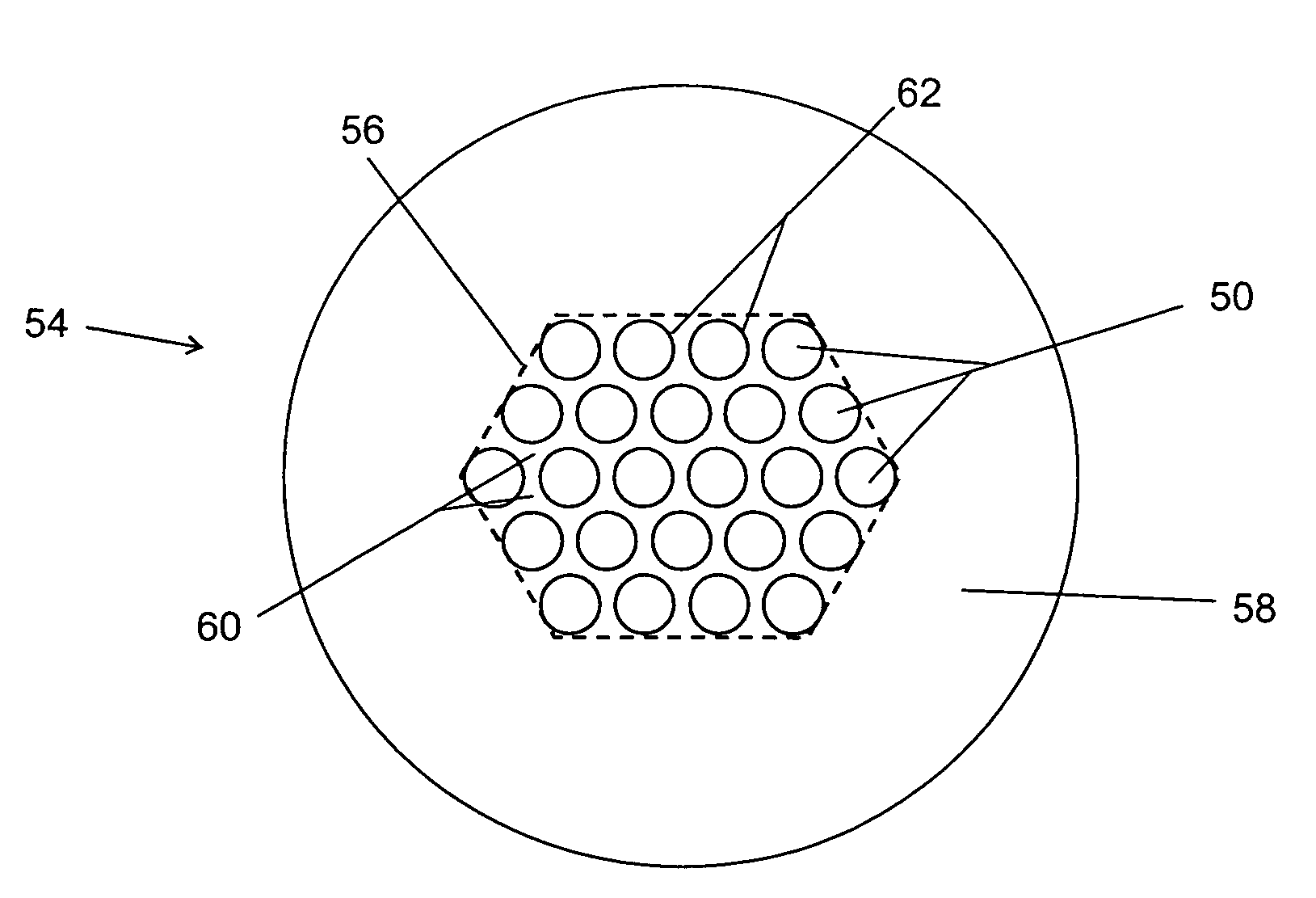
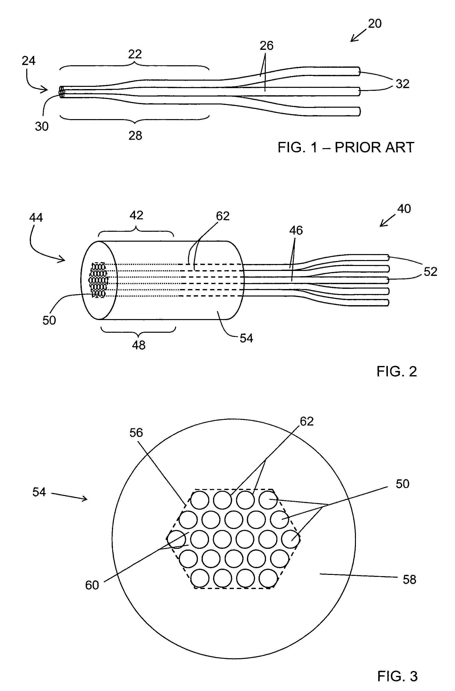
[0032]An example of a fused fiber bundle according to one embodiment of the present invention is shown in schematic side view in FIG. 2, and in end-on schematic view in FIG. 3. Fused fiber bundle 40 has a terminal section 42, ending with an endface 44. Fused fiber bundle 40 includes a plurality of optical fibers 46, each of which has a terminal segment 48 ending with a proximal end 50, and a distal end 52. Fused fiber bundle 40 also includes a cellular holding structure 54, which includes a cellular web portion 56 and a tube portion 58 surrounding the cellular web portion 56. The cellular web portion 56 is formed from a web material 60, and includes a plurality of longitudinal cells 62 arranged substantially in parallel, each surrounded by the web material 60. The terminal segments 48 of optical fibers 46 are arranged substantially in parallel, and each terminal segment 48 is disposed in a longitudinal cell 62 of the cellular holding structure 54. The terminal segments 48 of optical...


PUM

PropertyMeasurementUnit
thicknessaaaaaaaaaa
softening pointaaaaaaaaaa
cross-sectional areaaaaaaaaaaa

Abstract

The present invention relates to fiber bundles and methods for making fiber bundles. According to one embodiment of the invention, a fused fiber bundle has a terminal section ending with an endface, and includes a plurality of optical fibers, each of the optical fibers having a terminal segment ending with a proximal end, and a distal end; and a cellular holding structure, the cellular holding structure including a cellular web portion having a plurality of longitudinal cells arranged substantially in parallel and surrounded by a web material; and a tube portion surrounding the cellular web portion. The terminal segments of the optical fibers are arranged substantially in parallel, and the terminal segment of each optical fiber is disposed in a longitudinal cell of the cellular holding structure and substantially fused to the web material, thereby forming the terminal section of the fused fiber bundle.

Description

BACKGROUND OF THE INVENTION[0001]1. Field of the Invention[0002]The present invention relates generally to devices for transporting light. More specifically, the invention relates to fiber bundles and methods for making fiber bundles.[0003]2. Technical Background[0004]In the fields of optical communication, laser machining, and optical sensing, it is often desirable to combine optical power from several sources into a single beam. For example, in sensing applications, a fiber bundle can be used to combine optical power of different wavelengths from different laser or lamp sources into a single beam. In certain high-power applications, a fiber bundle can combine optical power from several identical sources into a single beam of relatively high power. Fiber bundles may also be used to divide light from a single source into a plurality of beams, or to reshape a beam in order to couple it between different optical devices.[0005]A conventional fiber bundle is shown in FIG. 1. Fiber bundl...

Claims


Application Information

Patent Timeline
Patent Type & Authority Patents(United States)
IPC IPC(8): G02B6/04G02B6/02
CPCC03B23/207G02B6/06G02B6/2821H01S3/094007H01S3/094053
Inventor RASMUSSEN, MICHAEL HEATH
Owner CORNING INC
Why Eureka
Try Eureka