Method of forming a phase change memory device having a small area of contact

a technology of phase change memory and contact area, which is applied in the manufacturing of semiconductor/solid-state devices, electrical equipment, basic electric elements, etc., can solve the problems of increasing the cell coupling rate and the degree of integration of flash memory devices

Active Publication Date: 2006-03-02
SAMSUNG ELECTRONICS CO LTD
View PDF17 Cites 94 Cited by
  • Summary
  • Abstract
  • Description
  • Claims
  • Application Information

AI Technical Summary

Benefits of technology

[0028]FIG. 1 is a cross-sectional view schematically illustrating a conventional phase change memory device.
[0029]FIG. 2 is a

Problems solved by technology

However, such tasks as the improvement of film quality and the increase of cell coupling r

Method used


Image

  • Method of forming a phase change memory device having a small area of contact
  • Method of forming a phase change memory device having a small area of contact
  • Method of forming a phase change memory device having a small area of contact

Examples


Embodiment Construction

[0038] The present invention will now be described more fully hereinafter with reference to the accompanying drawings, in which preferred embodiments of the invention are shown. In the drawings, the thickness of layers and regions are exaggerated for clarity. In addition, when a layer is described to be formed on other layer or on a substrate, which means that the layer may be formed on the other layer or on the substrate, or a third layer may be interposed between the layer and the other layer or the substrate. Like numbers refer to like elements throughout the specification.

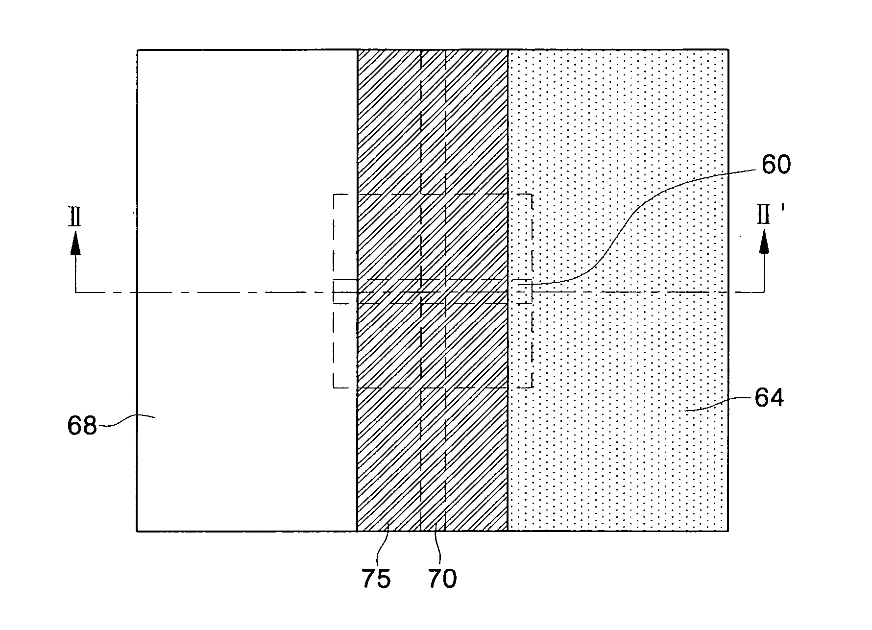
[0039] FIGS. 5 to 24 are plan views and cross-sectional views in a process order illustrating methods of fabricating a phase change memory device in accordance with embodiments of the present invention. Specifically, FIGS. 5, 7, 9, 11, 13, 15, 17, 19, 21, and 23 are schematic plan views illustrating a portion of a semiconductor substrate in a process order of methods of fabricating a phase change memory device...


PUM


Abstract

Methods of fabricating a phase change memory device having a small area of contact are provided. The method includes forming a lower interlayer insulating layer on a semiconductor substrate, and forming a lower conductor pattern within the lower inter-insulating layer. A first insulating layer pattern which crosses a top surface of the lower conductor pattern is formed on the semiconductor substrate having the lower conductor pattern. A conductive spacer pattern electrically connected to the lower conductor pattern is formed on a sidewall of the first insulating layer pattern. A first interlayer insulating layer is formed on the semiconductor substrate having the conductive spacer pattern. The first interlayer insulating layer and the conductive spacer pattern are planarized to form a bottom electrode. A second insulating layer pattern which crosses a top surface of the bottom electrode and exposes a portion of the bottom electrode is formed on the semiconductor substrate having the bottom electrode. A phase change material spacer electrically connected to the bottom electrode is formed on a sidewall of the second insulating layer pattern. A second interlayer insulating layer is formed on the semiconductor substrate having the phase change material spacer. The second interlayer insulating layer and the phase change material spacer are planarized to form a phase change material pattern.

Description

CROSS-REFERENCE TO RELATED APPLICATION [0001] This application claims the benefit of Korean Patent Application No. 2004-0069361, filed Aug. 31, 2004, the contents of which are hereby incorporated herein by reference in their entirety. BACKGROUND OF THE INVENTION [0002] 1. Field of the Invention [0003] The present invention relates to methods of fabricating a semiconductor memory device and, more particularly, to methods of fabricating a phase change memory device having a small area of contact. [0004] 2. Description of the Related Art [0005] Semiconductor memory devices may be classified as volatile memory devices or non-volatile memory devices, depending on whether data is retained when the power supply is interrupted. The non-volatile memory device has an advantage in that data stored therein is not erased even when the power supply is interrupted. Accordingly, the non-volatile memory device is widely employed in a mobile communication system, a memory card, and so forth. [0006] A...

Claims


Application Information

Patent Timeline
IPC IPC(8): H01L21/31H01L21/469
CPCH01L45/06H01L45/124H01L45/1691H01L45/144H01L45/1273H10N70/8265H10N70/8418H10N70/231H10N70/068H10N70/8828H10B99/00
Inventor GWAN-HYEOB, KOH
Owner SAMSUNG ELECTRONICS CO LTD
Why Eureka
Try Eureka