
Soft mesh lacrosse head pocket having selectively coated strings

Active Publication Date: 2006-03-02
WM T BURNETT IP
View PDF13 Cites 29 Cited by
  • Summary
  • Abstract
  • Description
  • Claims
  • Application Information

AI Technical Summary

Benefits of technology

[0012] The present invention provides a lacrosse stick mesh pocket that eliminates or minimizes many of the drawbacks of soft mesh pockets and hard mesh pockets, while providing many of the advantages of each. In particular, the present invention provides a soft mesh pocket that is selectively coated in strategic locations, to provide performance advantages traditionally associated with soft and hard mesh pockets, but without introducing the disadvantages of each. In this manner, the present invention provides a mesh lacrosse head pocket that has the throwing and shooting characteristics of hard mesh and the ball dislodgement characteristics of soft mesh.

Problems solved by technology

In addition to supporting the pocket stringing, the throwing strings prevent the thrown ball from traveling too far up the pocket assembly and striking the scoop, which can cause inaccurate passing and shooting.
This less structured pocket, however, can also can make it more difficult to shoot and pass.
As the ball rolls from the stop member of the head toward the scoop, the soft mesh's tendency to sag hampers the release of the ball.
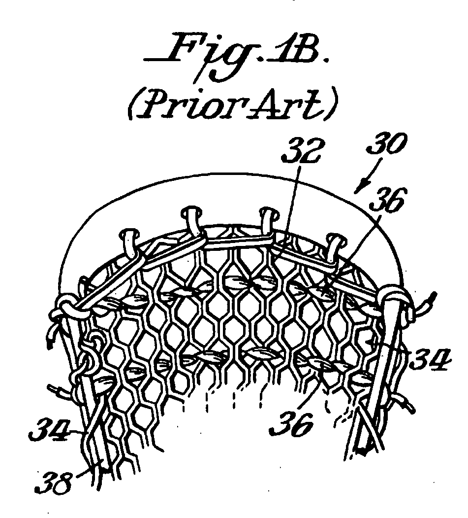
While interweaving shooting strings across the mesh can reduce this sagging effect, the soft mesh may still not support the heavy lacrosse ball, allowing the ball to get caught under (or being impeded rather than assisted by) the throwing strings.
In addition, the throwing strings add another stringing member to the pocket, which adds weight to the lacrosse head and increases the time and effort needed to maintain the pocket.
The traditional throwing string materials also tend to rot, break, crack, wear out, absorb water, and stretch due to weather conditions and the constant wear and tear of catching and throwing a lacrosse ball.
In addition, the traditional throwing strings are difficult to adjust since they require the loosening of knots made to hold them in place and a tedious adjustment process along the portions of the throwing strings that are interwoven among the mesh diamonds.
Forming the pocket of hard mesh, however, makes it more difficult to catch and retain the ball in the pocket.

Method used


Image

  • Soft mesh lacrosse head pocket having selectively coated strings
  • Soft mesh lacrosse head pocket having selectively coated strings
  • Soft mesh lacrosse head pocket having selectively coated strings

Examples


Embodiment Construction

[0027]FIG. 2 illustrates a lacrosse head 200 having a soft mesh pocket 201 with a portion of its strings coated to define a ball release area, according to an embodiment of the present invention. As shown, lacrosse head 200 includes a scoop 202, sidewalls 204 and 206 connected to scoop 202, and a stop member 208 connected to sidewalls 204 and 206. Together, scoop 202, sidewalls 204 and 206, and stop member 208 define the frame of lacrosse head 200. The frame defines an interior area in which the mesh pocket 201 is disposed. As shown, the mesh pocket is preferably disposed within the frame from proximate scoop 202 to proximate stop member 208 and from proximate sidewall 204 to proximate sidewall 206, thereby covering substantially the whole interior area of the frame.

[0028] In the example of FIG. 2, mesh pocket 201 is attached to head 200 using a lacing 210. Optionally, pocket 201 could attach directly to head 200 or through some other binding means (e.g., multiple stringing cords o...


PUM


Abstract

A lacrosse head having a soft mesh pocket with an area of its strings coated with stiffening material. The coated area defines, for example, a ball release area, a ball pocket, and / or a throwing channel. One embodiment provides a lacrosse head pocket that includes a continuous piece of mesh, and a stiffening material coating a first area of the mesh, with a second area of the mesh being uncoated. The first area defines, for example, a ball release area, a ball pocket, and / or a throwing channel.

Description

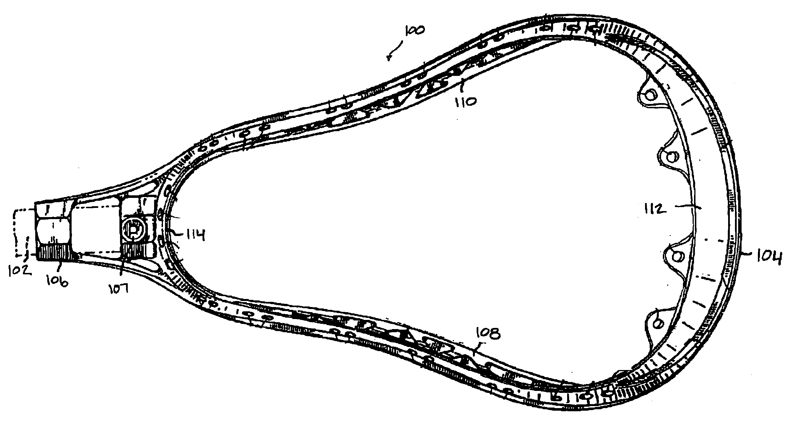
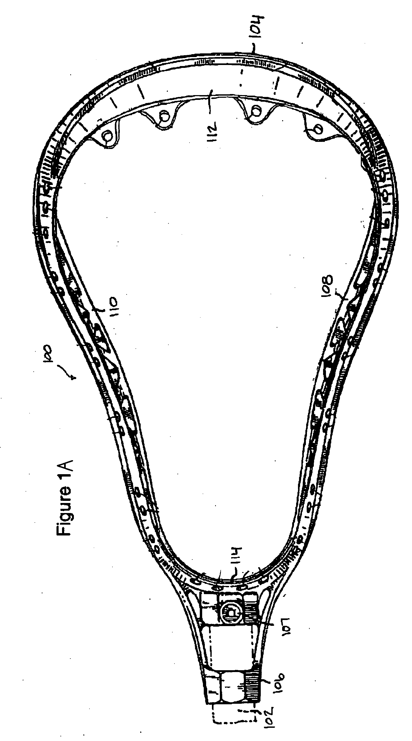
BACKGROUND [0001] 1. Field of the Invention [0002] The present invention relates generally to lacrosse sticks, and more particularly, to a lacrosse head having a soft mesh pocket with selectively coated strings. [0003] 2. Background of the Invention [0004]FIG. 1A illustrates a conventional lacrosse stick 100 having a handle 102 shown in dotted lines and a double-wall synthetic head 104. Head 104 comprises a generally V-shaped frame having a juncture 106, sidewalls 108 and 110, a transverse wall (or “scoop”) 112 joining the sidewalls at their ends opposite juncture 106, and a stop member 114 joining sidewalls 108 and 110 at their ends nearest juncture 106. As shown, handle 102 fits into and through juncture 106, and abuts stop member 114. A screw or other fastener placed through opening 107 secures handle 102 to head 104. The typical features of a lacrosse stick are shown generally in Tucker et al., U.S. Pat. No. 3,507,495, Crawford et al., U.S. Pat. No. 4,034,984, and Tucker et al.,...

Claims


Application Information

Patent Timeline
IPC IPC(8): A63B59/02A63B65/12
CPCA63B59/02A63B59/20A63B51/02A63B2102/14
Inventor TUCKER, RICHARD B. C. JR.
Owner WM T BURNETT IP
Learn More