Universally adjustable gun rack and lock assembly

a universal adjustable, gun rack technology, applied in the field of gun racks and locks, can solve the problems of inability to move the gun lock, the problem of easy access to the weapon, and the inability to store such weapons in the hom

Active Publication Date: 2006-03-09
SANTA CRUZ GUNLOCKS
View PDF16 Cites 41 Cited by
  • Summary
  • Abstract
  • Description
  • Claims
  • Application Information

AI Technical Summary

Benefits of technology

[0020] Another aspect of the invention is to provide a gun lock that has a solenoid that can be activ

Problems solved by technology

Yet, easy access to the weapon can present a problem, for example, if an intruder or other unauthorized person attempted to misappropriate the weapon.
Further complicating the problem is the fact that whereas in the past, law enforcement personnel generally carried only one type of weapon, typically a service revolver.
Storage of such weapons in the home presents the same problems.
A problem with all of these presently available devices is that they are pre-sized to accommodate only one type of firearm.
Further, once affixed, the gun lock cannot be moved relative to its mounting position nor can the lock grab any cross-section of any weapon to achieve one lock that fits all weapons and locking situations.
However, this reference does not disclose or suggest the advantage of having the locking portion of the device being able to slide relative to t

Method used


Image

  • Universally adjustable gun rack and lock assembly
  • Universally adjustable gun rack and lock assembly
  • Universally adjustable gun rack and lock assembly

Examples


Embodiment Construction

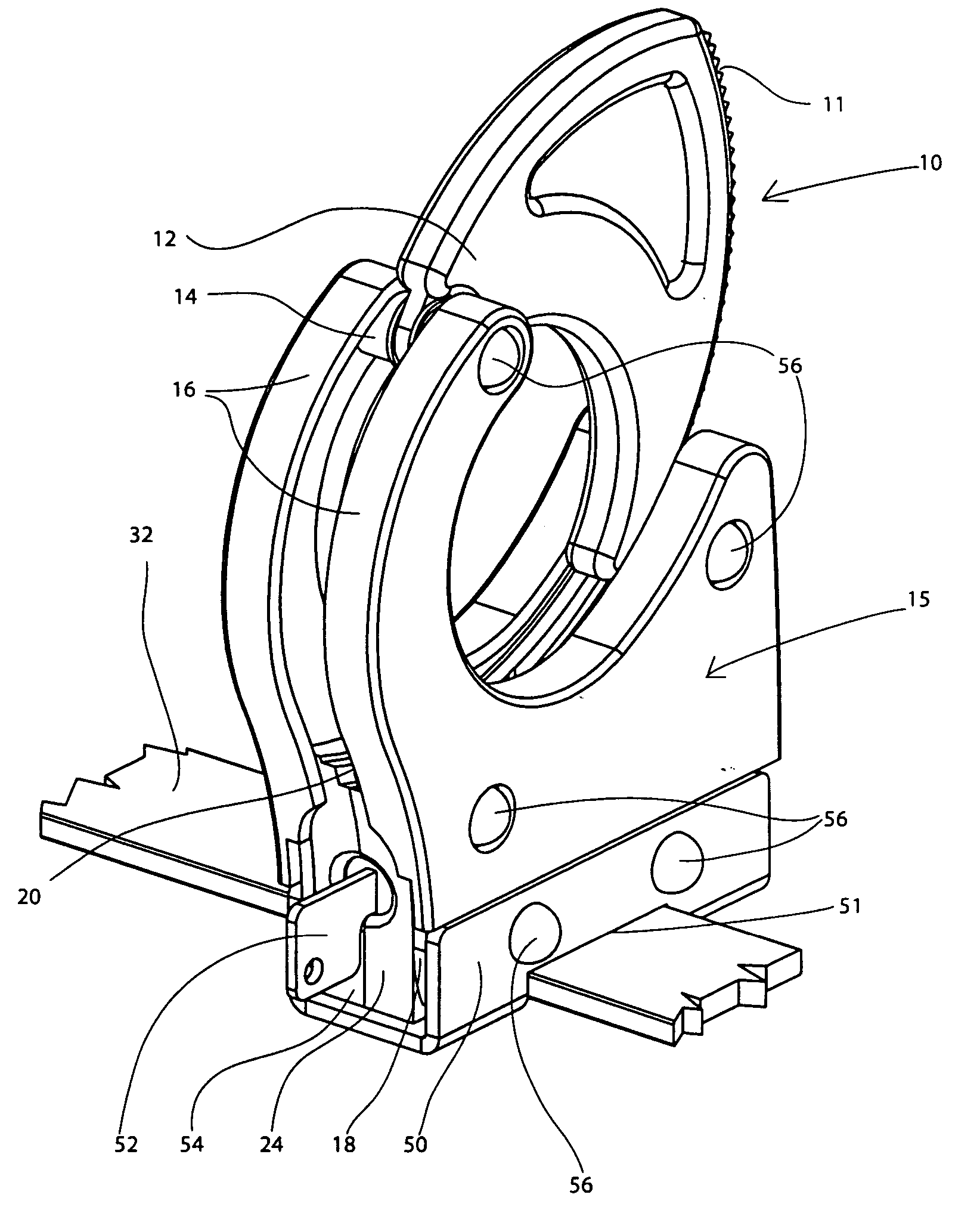
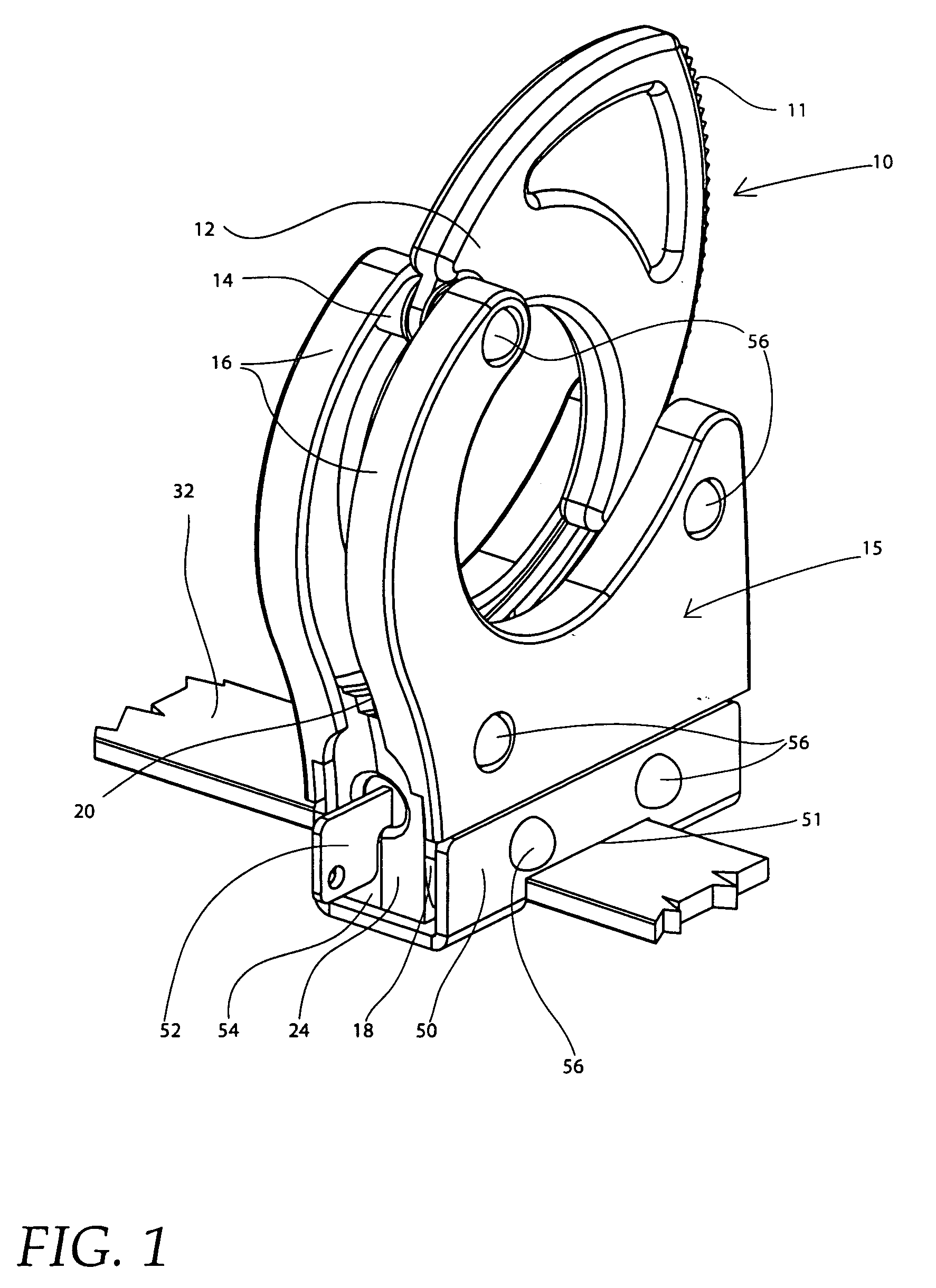
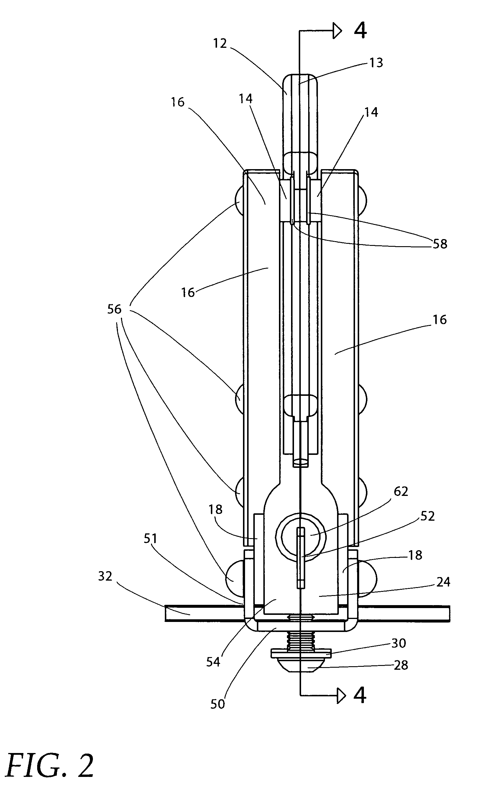
[0030] Referring to FIGS. 1-5, the universal adjustable gun lock apparatus 10 is shown. Typical the apparatus 10 is mounted to a storage surface. If that storage surface is in a law enforcement officer's vehicle, the ceiling of the vehicle is generally used. However, the apparatus can be mounted vertically as well. Most importantly, the apparatus 10 can be used in any location where it is desired to securely store a weapon.

[0031] The apparatus 10 comprises mounting slide bar or track 32 and locking assembly 15. Locking assembly 15 is slidably affixed to slide bar 32 and at any desired location and supports the firearm 72 generally parallel to slide bar 32 as shown in FIG. 5. Slide bar 32 is preferably solid steel having a relatively small thickness compared to its width. In this manner, the profile of slide bar 32 is compact thus keeping the weapon close to the surface that it is mounted thereon.

[0032] Note that the apparatus can be used at angle relative to the axial length of th...


PUM


Abstract

A gun lock for receiving and clamping a cross-sectional portion of a firearm. A slide bar is provided for mounting the gun lock to a surface in a storage location such as a motor vehicle, home, office, a cabinet or any surface where a gun might be stored. A locking assembly slidably mountable to the slide bar is provided. A pivotably attachable ratchet arm which resembles typical handcuffs is provided. One arm has a plurality of ratchet teeth that enables the gun lock to clamp a wide variety of cross-sectional portions of weapons having different configurations. A solenoid activatable locking assembly is positioned within the lock. The solenoid has a plunger adapted to engage one of the ratchet teeth of the ratchet arm to lock the rotatable ratchet arm in position around the cross-sectional portion of the weapon to be locked. The solenoid locking assembly is releasable via a switch. A manual override assembly is also provided. The manual override assembly is activated with a key. Once the key is turned, a camlock that is connected to the plunger of the solenoid locking assembly causes the plunger to move. When the key is turned in one direction, the arm rotates and the plunger disengages from the ratchet teeth of the ratchet arm. When the key is turned in the opposite direction, the plunger again engages one of the ratchet teeth to again lock the locking assembly. A set screw assembly for releasably locking the locking assembly onto the sliding bar is provided. A set screw and a set screw nut locks the locking assembly onto the slide bar. The set screw is accessible by a hex key through an opening in housing of the apparatus only when the ratchet arm is in the unlocked open position.

Description

FIELD OF THE INVENTION [0001] This invention relates to gun racks and locks, and, more particularly, to gun racks and locks adapted to mount long guns, such as shot gun and rifles. BACKGROUND OF THE INVENTION [0002] Law enforcement personnel often carry firearms in their vehicles. These weapons, which include shot guns, rifles, assault rifles and other types of long guns, are often stored in a gun lock fastened securely to a gun rack. The gun rack is mounted either horizontally or vertically at an interior location in the vehicle, and generally is mounted in substantially parallel to a planar region serving as the mounting base in the vehicle, such as the floor, a sidewall or the ceiling. [0003] The design of the storing assembly must provide for immediate release of the weapon when needed by the law enforcement officer. Yet, easy access to the weapon can present a problem, for example, if an intruder or other unauthorized person attempted to misappropriate the weapon. [0004] Furthe...

Claims


Application Information

Patent Timeline
IPC IPC(8): E05B73/00
CPCE05B15/0046E05B73/00Y10S224/913F41C33/06E05B73/0041B60R7/14F41A23/18Y10T70/404Y10T70/409Y10T70/411Y10T70/5009Y10T70/5027Y10T70/7107
Inventor TANOS, LASZLO
Owner SANTA CRUZ GUNLOCKS
Why Eureka
Try Eureka