Wick structure of heat pipe

Inactive Publication Date: 2006-03-09
HSU HUL CHUN
View PDF10 Cites 8 Cited by
  • Summary
  • Abstract
  • Description
  • Claims
  • Application Information

AI Technical Summary

Benefits of technology

[0005] The present invention provides a wick structure of a heat pipe with different sized woven fibers. The woven fibers include a plurality of orthogonal transversal fibers and longitudinal fibers and the transversal fibers are thicker than the longitudinal fibers. When the wick structure is attached on the internal sidewall of the heat pipe, the longitudinal fibers are extended along the axial direction of the heat pipe. Therefore, the tubular heat pipe with one end contacted with the heat source can provide good capillary force to enhance the re-flowing rate of the working fluid filled in the heat pipe from the other end because of the thinner longitudinal fibers of woven wick. On the other hand, the thicker transversal fibers can provide more support to the longitudinal fibers so as to enhance the attachment of the wick structure to the heat pipe.

Problems solved by technology

Therefore, both of good capillary force and well attaching capability providing by the wick structure can not be reached at the same time.
Alternatively, thinner woven fibers can provide good capillary action but can not provide good support to be attached on the internal sidewall of the tubular member of the heat pipe.

Method used


Image

  • Wick structure of heat pipe
  • Wick structure of heat pipe
  • Wick structure of heat pipe

Examples


Embodiment Construction

[0016] Reference will now be made in detail to the preferred embodiments of the present invention, examples of which are illustrated in the accompanying drawings. Wherever possible, the same reference numbers are used in the drawings and the description to refer to the same or like parts.

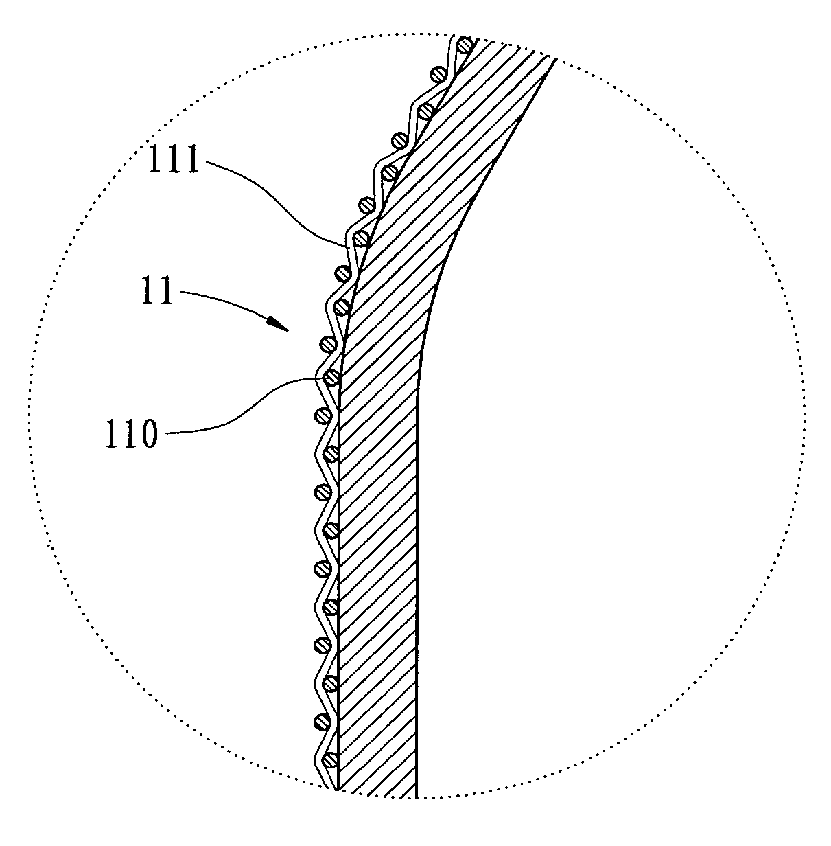
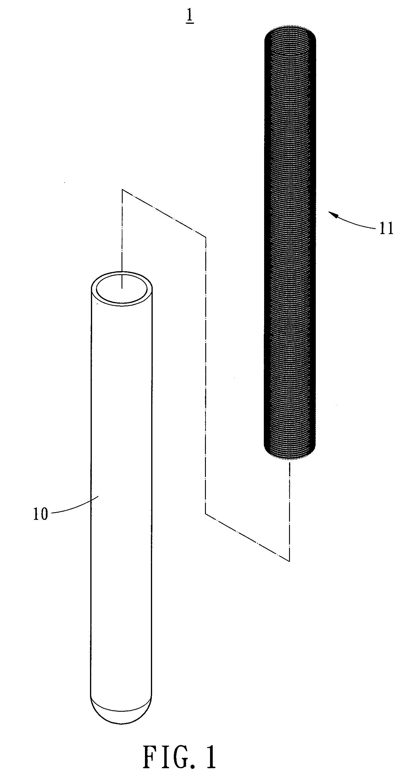
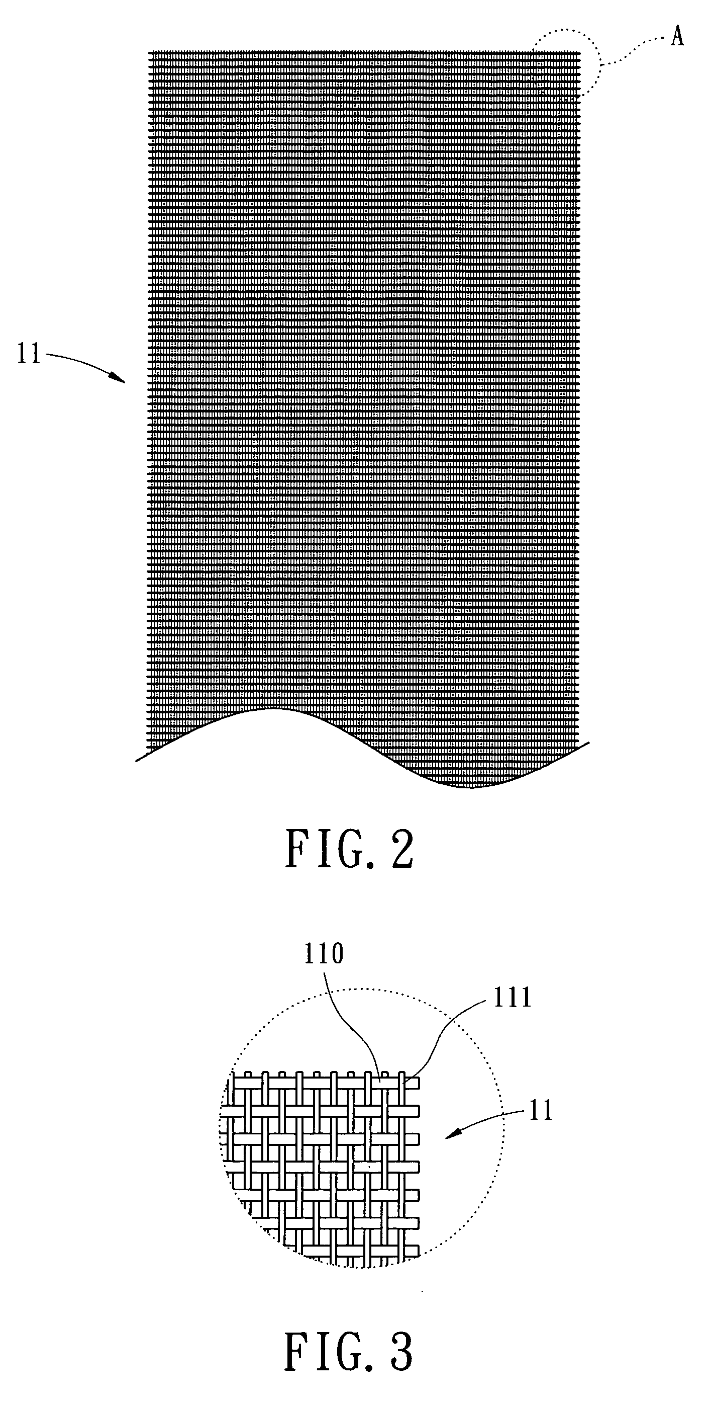
[0017] Please refer to FIGS. 1 and 2, which respectively show an exploded view of a heat pipe and an expanded view of a wick structure according to the present invention. The heat pipe 1 includes a tubular member 10 with a wick structure 11 attached on the internal sidewall thereof. The wick structure 11 includes at least one layer of woven wick formed by a plurality of orthogonal fibers 110 and 111 as shown in FIG. 3. Such that, while the wick structure 11 is attached on the internal sidewall of the tubular member 10, the longitudinal fibers 111 are arranged extending along the axial direction of the tubular member 10. The woven fibers 110 and 111 are preferably made of metal material with higher ...


PUM

PropertyMeasurementUnit
Structureaaaaaaaaaa

Abstract

A wick structure is attached on an internal sidewall of a heat pipe. The wick structure includes a plurality of orthogonal woven fibers. The fibers extending along a longitudinal direction of the heat pipe are thinner; therefore the wick structure is capably of providing enhanced capillary action and good attachment to the heat pipe.

Description

BACKGROUND OF THE INVENTION [0001] The present invention relates in general to a wick structure of a heat pipe, and more particularly, to a wick structure capably of providing enhanced capillary action and good attachment to a heat pipe. [0002] There are lots of device used for transferring heat in the industry. A heat pipe is widely in the form of a tube with one closed end and one open end. A wick structure is installed in the heat pipe and a working fluid is introduced into the heat pipe, followed by the process of sealing the open end. When the heat pipe is in contact with the electronic products, the heat absorbing end absorbs the heat from the electronic products, such that a phase transition from the liquid state to the gas state occurs to the working fluid. After flowing to the cooling end of the heat pipe, the gaseous working fluid is then condensed back to the liquid state and re-flows back to the heat absorbing end by the capillary effect provided by the wick structure. T...

Claims


Application Information

Patent Timeline
IPC IPC(8): F28D15/00
CPCF28D15/0233Y10T29/49353F28D15/046
Inventor HSU, HUL-CHUN
Owner HSU HUL CHUN
Why Eureka
Try Eureka